
Device and method for realizing lateral earth pressure in pile foundation model test

A lateral earth pressure and model test technology, which is applied in the test of foundation structure, foundation structure engineering, construction, etc., can solve the problems of large model size, the power capacity of the centrifuge cannot meet the requirements of the test, and the similar conditions are difficult. achieve the effect of avoiding mutual blocking

Active Publication Date: 2022-05-06
GUANGZHOU INSTITUTE OF BUILDING SCIENCE CO LTD +1
View PDF5 Cites 0 Cited by
  • Summary
  • Abstract
  • Description
  • Claims
  • Application Information

AI Technical Summary

Problems solved by technology

In the simulation test of similar materials considering its own weight, the model test and the prototype must be similar in terms of material strength, bulk density, geometric size, denaturation properties, stress state, etc., and certain constraints must be satisfied between the similarity ratios. It is difficult to satisfy these similar conditions simultaneously
In order to obtain a specific stress field, the method of centrifuge test is generally used, but in the pile foundation model test, in order to truly reflect the actual pile-soil interaction and the effect of pile side grouting, the scale of the model test is small, so that The size of the model is large and the weight is heavy. At this time, the dynamic capacity of the centrifuge cannot meet the requirements of the test, and the lateral earth pressure in the soil has an important influence on the friction between the pile and soil and the shape of the pile-soil cemented surface. , if the actual stress field cannot be obtained, such test results are difficult to use to evaluate the actual mechanical behavior and engineering characteristics of the engineering prototype

Method used


Image

  • Device and method for realizing lateral earth pressure in pile foundation model test
  • Device and method for realizing lateral earth pressure in pile foundation model test
  • Device and method for realizing lateral earth pressure in pile foundation model test

Examples


Embodiment

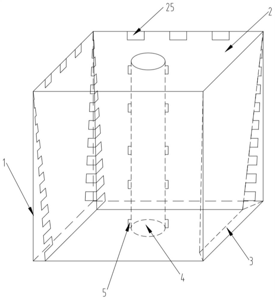
[0029] like Figure 1 to Figure 5 As shown, the device for realizing lateral earth pressure in the pile foundation model test described in this embodiment includes a model box 1, four lateral pressure transfer plates 2, four pressurized airbags 3 model piles 4, and a plurality of earth pressure sensor 5. Model piles 4 , four lateral pressure transfer plates 2 , four pressurized airbags 3 and multiple earth pressure sensors 5 are placed in the model box 1 , and soil fills the space in the model box 1 .

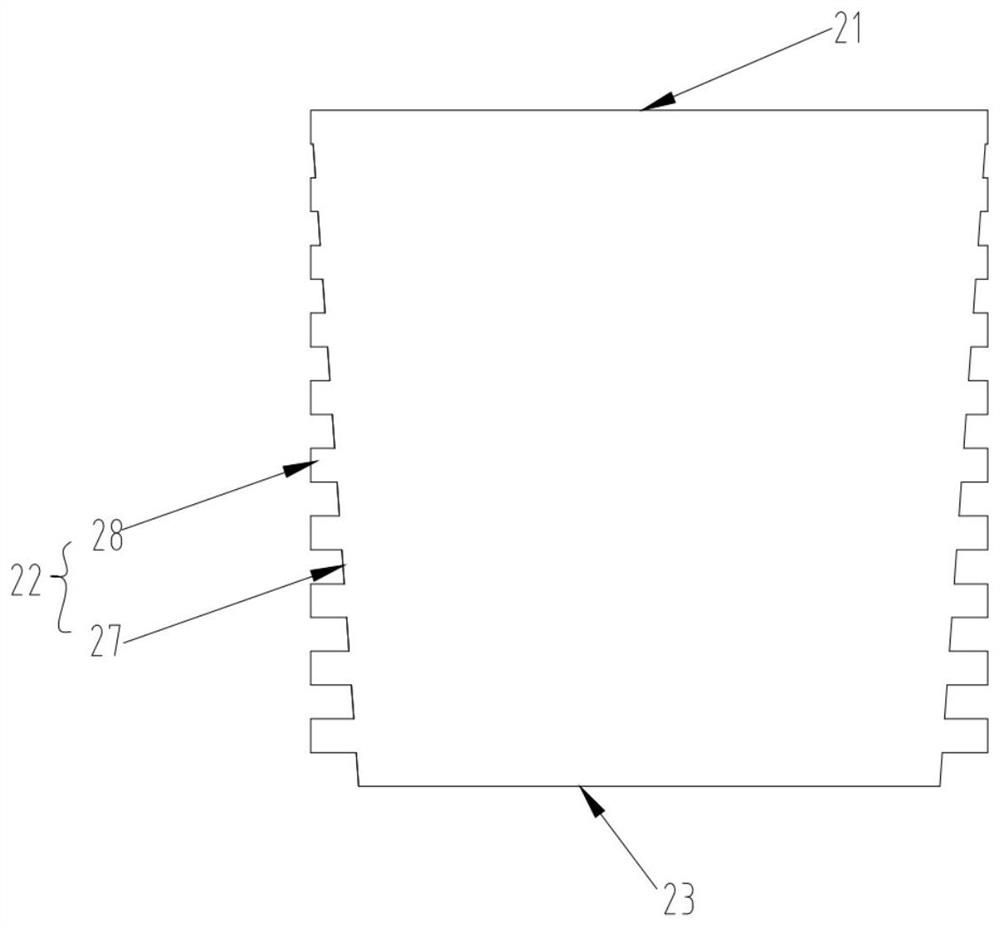
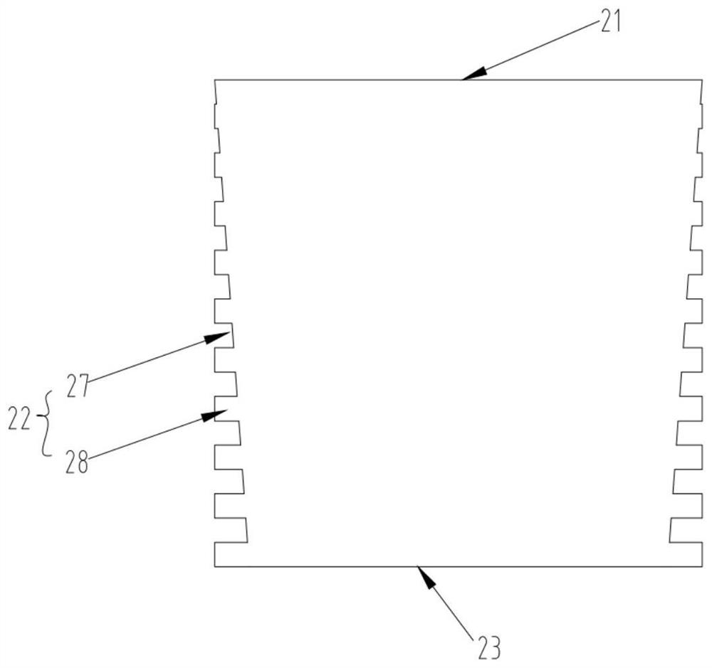
[0030] Among them, such as figure 2 and image 3 as shown, figure 2 and image 3 It is the lateral pressure transfer plate 2 that matches and engages with each other. The side pressure transmission plate 2 is a square plate body with four sides, namely a connecting side 21 , an occlusal side 22 , a swinging side 23 and another occlusal side 22 . On the same lateral pressure transmission plate 2, the connecting side 21 and the swinging side 23 form a pair of opposite sid...


PUM


Abstract

The invention discloses a device for realizing lateral earth pressure in a pile foundation model test, comprising a model box, a model pile, a plurality of lateral pressure transfer plates, a plurality of pressurizing equipment and a plurality of earth pressure sensors, the model pile, The side pressure transmission plate, pressurization equipment and earth pressure sensor are placed in the model box; one side of the side pressure transmission plate is movably connected with the side wall of the model box, and the two adjacent side walls of the model box The side pressure transmission plate on the upper part is snapped and connected, and the pressurization device is arranged between the side wall of the model box and the side pressure transmission plate on the side wall; the model pile is placed on the side pressure transmission plate. In the space enclosed by the slab, the earth pressure sensor is arranged on the model pile. The invention does not need a centrifuge, and can also realize the simulation of the actual lateral earth pressure field in the model test.

Description

technical field [0001] The invention belongs to the technical field of pile foundation model tests in geotechnical engineering, in particular to a device and method for realizing lateral earth pressure in pile foundation model tests. Background technique [0002] In pile foundation engineering problems, the stress field generated by self-weight often plays a leading role in the deformation, strength and stability of the pile structure and the surrounding medium. In the simulation test of similar materials considering its own weight, the model test and the prototype must be similar in terms of material strength, bulk density, geometric size, denaturation properties, stress state, etc., and certain constraints must be satisfied between the similarity ratios. Simultaneously satisfying these similar conditions is difficult. In order to obtain a specific stress field, the method of centrifuge test is generally used, but in the pile foundation model test, in order to truly reflec...

Claims


Application Information

Patent Timeline
Patent Type & Authority Patents(China)
IPC IPC(8): E02D33/00
CPCE02D33/00
Inventor 侯明勋胡贺松唐孟雄
Owner GUANGZHOU INSTITUTE OF BUILDING SCIENCE CO LTD
Learn More