A blind spot detection device for a vehicle

A detection device and blind spot technology, applied in vehicle parts, optical observation devices, transportation and packaging, etc., can solve the problems of cumbersome replacement process, poor flexibility in changing lens angles, and high cost, and achieve enhanced flexibility, simple and practical structure, and high cost. low effect

Active Publication Date: 2019-05-14
ZHEJIANG GEELY HLDG GRP CO LTD +1
View PDF5 Cites 0 Cited by
  • Summary
  • Abstract
  • Description
  • Claims
  • Application Information

AI Technical Summary

Problems solved by technology

[0004] An object of the present invention is to provide a blind spot detection device for vehicles to solve the problems of high cost, cumbersome replacement process and poor flexibility of lens angle changes in existing blind spot detection devices.

Method used


Image

  • A blind spot detection device for a vehicle
  • A blind spot detection device for a vehicle
  • A blind spot detection device for a vehicle

Examples


Embodiment Construction

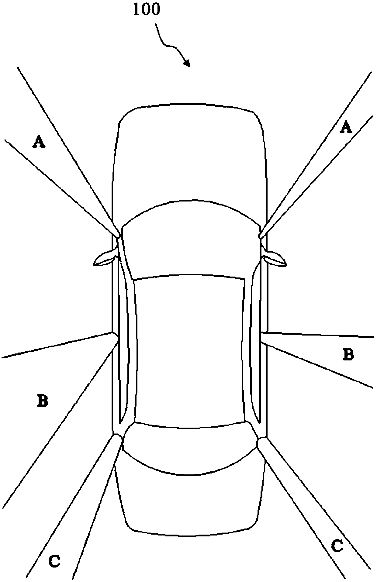
[0047] figure 1 is a schematic top view of the blind spot of the vehicle 100 . Such as figure 1 As shown, A represents the A-pillar blind area, B represents the B-pillar blind area, and C represents the C-pillar blind area. Generally, there are three types of pillars in the body of a car. From front to rear, there are front pillar 110 (A pillar), middle pillar (B pillar) and rear pillar (C pillar). For a car, the column not only acts as a support, but also acts as a door frame. The A-pillar, B-pillar and C-pillar are common knowledge in the field, and will not be described in detail here. The blind zone caused by the A-pillar is called the A-pillar blind zone. The blind zone caused by the B-pillar is called the B-pillar blind zone. The blind zone caused by the C-pillar is called the C-pillar blind zone. For safety considerations of the vehicle 100 , the B-pillar is generally relatively thick, and the angle of the rearview mirror is limited, so the B-pillar blind area is...


PUM


Abstract

The invention provides a blind zone detection device for a vehicle, and belongs to the field of auxiliary equipment for safe driving. The vehicle comprises front pillars and front door angle trim panels. The blind zone detection device comprises a drive motor and a mirror assembly, wherein the drive motor is equipped with an output shaft for outputting power; the mirror assembly is arranged on the front pillars or the front door angle trim panels and comprises a reflective surface for observing pillar B blind zones and a back surface opposite to the reflective surface, and the back surface is connected with one end of the output shaft; the mirror assembly is configured to be capable of deflecting around one end of the output shaft under the drive of the drive motor to change the observation range of the reflective surface of the mirror assembly. Due to the ingenious application of the mechanical structure, parts with high cost are prevented from being used, the cost is reduced, the blind zone detection device can be widely applied to the vehicle, other parts need not to be disassembled during disassembly, and the disassembly efficiency is improved.

Description

technical field [0001] The invention relates to the field of auxiliary equipment for safe driving, in particular to a blind spot detection device for vehicles. Background technique [0002] Vehicles, such as automobiles, equipped with conventional side and rear view mirrors have blind spots or blind spots on the sides of these vehicles. Drivers looking straight ahead cannot see other vehicles in these blind spots either directly or in rearview or side mirrors. This can lead to dangerous situations and even accidents when the driver of the vehicle is unaware that there is another vehicle in the blind spot and tries to perform a maneuver, for example, changing lanes, overtaking maneuvers, turning left or right, etc. [0003] In order to solve or improve the safety performance of vehicles, blind spot detection devices are widely used. The blind spot detection devices may include, for example, three types. The first is to install a visible camera or radar at the exterior rear...

Claims


Application Information

Patent Timeline
Patent Type & Authority Patents(China)
IPC IPC(8): B60R1/04
CPCB60R1/04
Inventor 周迎辉杨全凯汤小生
Owner ZHEJIANG GEELY HLDG GRP CO LTD
Why Eureka
Try Eureka