
Vacuum Interrupter Pole for High Pressure Environment Applications

A vacuum interrupter and high-voltage environment technology, applied in the field of pole parts, to achieve the effect of tolerance compensation

Active Publication Date: 2019-07-05
ABB (SCHWEIZ) AG
View PDF5 Cites 0 Cited by
  • Summary
  • Abstract
  • Description
  • Claims
  • Application Information

AI Technical Summary

Problems solved by technology

The problem resides in the high pressure housing of the vacuum interrupter, which is usually ceramic

Method used


Image

  • Vacuum Interrupter Pole for High Pressure Environment Applications
  • Vacuum Interrupter Pole for High Pressure Environment Applications

Examples


Embodiment Construction

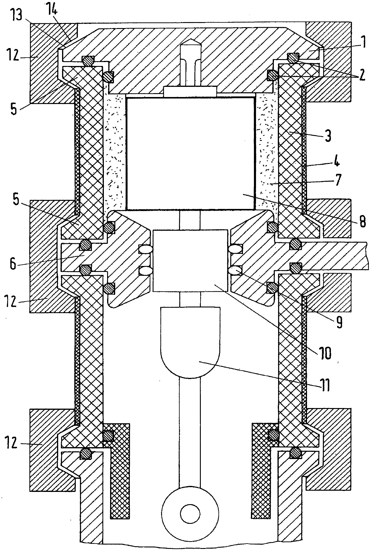
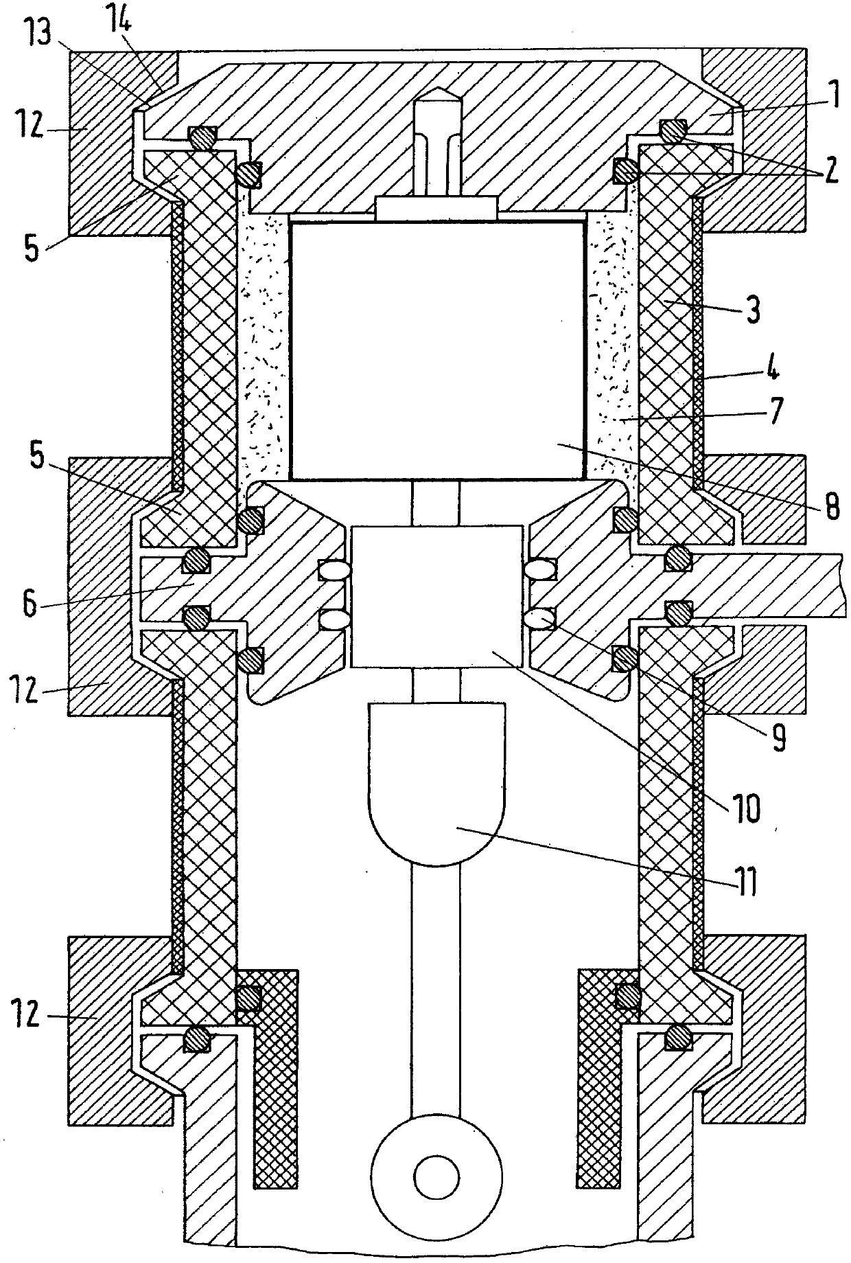
[0020] figure 1 Shown is an embedded pole part based on a ceramic housing as a high voltage part, wherein a vacuum interrupter 8 is mounted and inside the vacuum interrupter is provided with at least one moving contact and at least one stationary contact, and is provided with Terminated in an external contact rod or push rod 11 , which passes through the ceramic of the vacuum interrupter. In order to access the vacuum interrupter 8 from the outside, metal parts are mounted on both sides of the ceramic housing of the vacuum interrupter metal parts, and the connection from the ceramic housing to the place where the vacuum interrupter is connected is installed on the fixed contact side Department cover.

[0021] On the other side of the housing, a flange is provided at the ceramic part, which connects the movable side of the vacuum interrupter to the middle part of the flange by means of a sliding contact system 9 . Here, the electrical connection takes place and the connection...


PUM


Abstract

The invention relates to a pole part for use in high-voltage environments according to the preamble of claim 1, the pole part having a voltage-resistant insulating housing, in which a vacuum interrupter is installed, wherein the vacuum is interrupted The vacuum interrupter is provided with at least one moving contact and at least one stationary contact within the vacuum interrupter. In order to create pole parts with high environmental pressure resistance, the invention consists in that the pressure-resistant insulating casing is tubular and provided at its ends with flanges formed on the insulating casing from the same material, and in the flanges At least one of them is closed by a metal cover, which is adapted to the above-mentioned flange of the insulating housing with the same size, and by means of a clamping device, the metal cover is tightly pressed against the protrusion of the insulating housing by the clamping force introduced. edge.

Description

technical field [0001] The invention relates to a pole part for high-voltage environment applications according to the preamble of claim 1 , which has a voltage-resistant insulating housing in which a vacuum interrupter is installed. Background technique [0002] Medium pressure vacuum interrupters are known for use in high pressure environments, such as in subsea applications. The problem resides in the high pressure housing of the vacuum interrupter, which is usually ceramic. Contents of the invention [0003] The object of the invention is to create pole parts with high environmental pressure resistance by easier but very effective structural means. [0004] In order to solve this requirement, the present invention consists in that the pressure-resistant insulating housing is tubular and provided at its ends with flanges formed on the insulating housing from the same material, and at least one of the flanges is closed by a metal cover, The metal cover is fitted to the...

Claims


Application Information

Patent Timeline
Patent Type & Authority Patents(China)
IPC IPC(8): H01H33/66
CPCH01H33/6606H01H2033/66223H01H2033/6623H01H33/66207H01H33/664
Inventor D·金特施D·苏比亚西瓦尔
Owner ABB (SCHWEIZ) AG
Learn More