
Power system stabilizer (PSS) configuration method in coordination with low-excitation limiting function

A low-excitation limiting, power system technology, applied in the field of power systems, can solve the problems of the deterioration of the dynamic stability of the power system and the inability to achieve ideal effects, and achieve the effects of strong practicability, effective damping, and simple and convenient operation.

Active Publication Date: 2017-05-24
CHINA ELECTRIC POWER RES INST +2
View PDF1 Cites 14 Cited by
  • Summary
  • Abstract
  • Description
  • Claims
  • Application Information

AI Technical Summary

Problems solved by technology

[0004] Because the output signals of UEL and PSS are both output to the voltage superposition point of the excitation system, both of them participate in the excitation adjustment and affect each other during the dynamic process of the unit being disturbed. The traditional PSS parameters cannot achieve the desired effect. Many causes of UEL A case where the dynamic stability of the power system deteriorates

Method used


Image

  • Power system stabilizer (PSS) configuration method in coordination with low-excitation limiting function
  • Power system stabilizer (PSS) configuration method in coordination with low-excitation limiting function
  • Power system stabilizer (PSS) configuration method in coordination with low-excitation limiting function

Examples


Embodiment Construction

[0044] The present invention will be described in detail below in conjunction with specific examples.

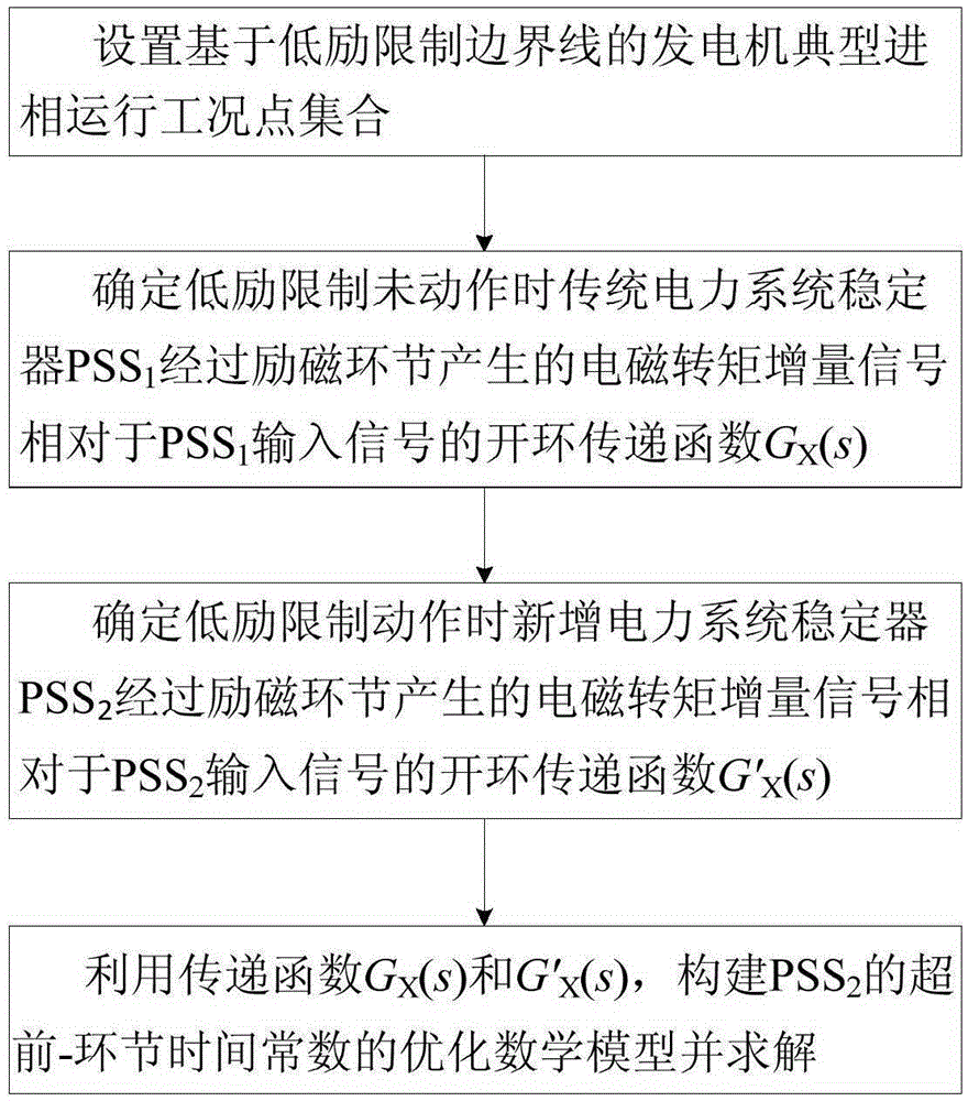
[0045] Such as figure 1 As shown, the present invention proposes a power system stabilizer configuration method coordinated with the low excitation limiting function, including:

[0046] (1) Set a set of typical advanced phase operating condition points of the generator based on the boundary line of the low excitation limit;

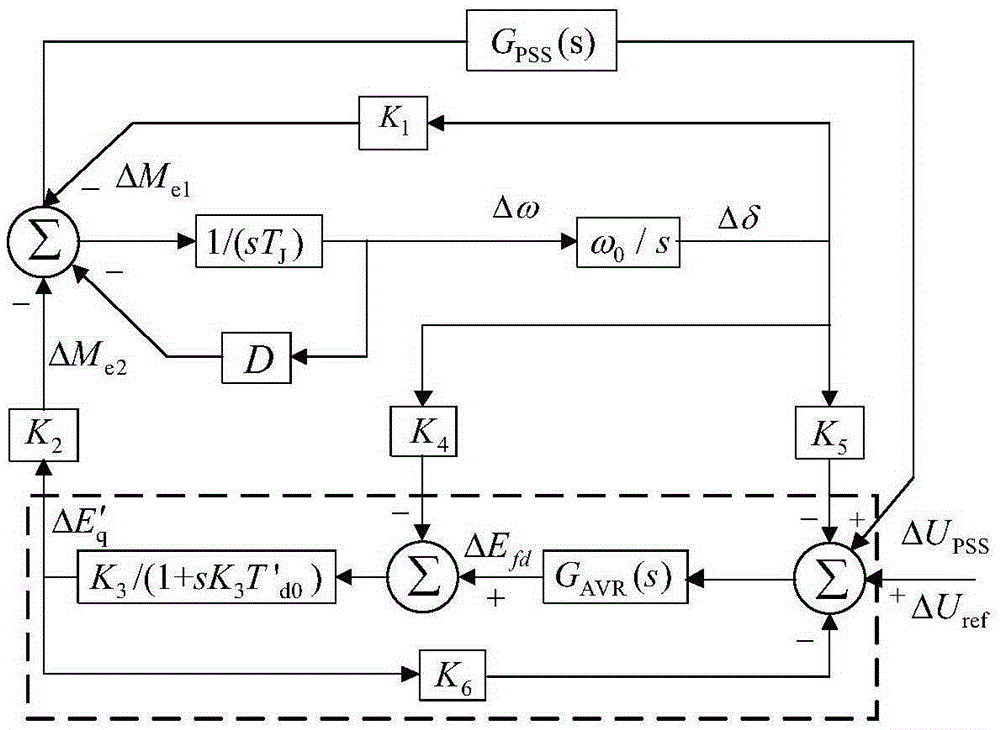
[0047] (2) Considering the traditional power system stabilizer PSS when the low excitation limit is not in action 1 Input situation, based on the stand-alone-infinite system Heffron-Phillips model, determine the PSS 1 The open-loop transfer function G of the electromagnetic torque incremental signal generated by the excitation link relative to the PSS input signal X (s);

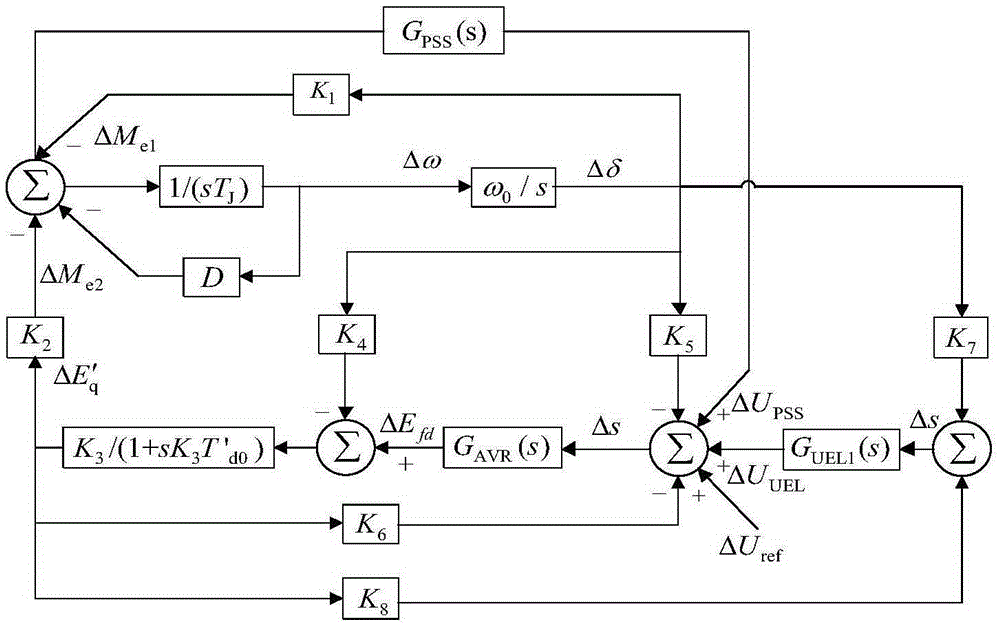
[0048] (3) Add power system stabilizer PSS when considering low excitation limit action 2 Input situation, based on the stand-alone-infinite system extended Heffron-Phillips mod...


PUM


Abstract

The invention relates to a power system stabilizer (PSS) configuration method in coordination with a low-excitation limiting function. The method is characterized by comprising steps: a generator typical leading phase operation working condition point set based on a low-excitation limiting boundary line is set; an open-loop transfer function G<X>(s) for electromagnetic torque increment signals generated by the traditional power system stabilizer PSS1 through an excitation link when low-excitation limiting does not act in relative to PSS1 input signals is determined; an open-loop transfer function G'<X>(s) for electromagnetic torque increment signals generated by the newly-added power system stabilizer PSS2 through an excitation link when low-excitation limiting acts in relative to PSS2 input signals is determined; and by using the transfer function G<X>(s) and the transfer function G'<X>(s), an optimal mathematical model for a lead-lag link time constant of the PSS2 is built and solved. The configuration method of the invention has the advantages that comprehensive factors are considered; the operation is simple and convenient; the practicability is strong; and the deteriorated dynamic stability of the power system caused as the low-excitation limiting acts can be effectively solved.

Description

technical field [0001] The invention relates to the field of power systems, in particular to a method for configuring a power system stabilizer coordinated with a low excitation limiting function. Background technique [0002] Under excitation limit (UEL) is an important auxiliary function in the excitation system. Its function is to prevent the generator from being unstable due to too deep phase advance, prevent the end of the stator core from overheating and reduce the malfunction of the generator loss of excitation protection. risk. UEL can be divided into superposition type and selective type according to the different ways of accessing the excitation system, and the former is more widely used at present. UEL is based on real-time active power P of the unit t , reactive power Q t and terminal voltage U t is the input variable. According to P t and U t Calculated real-time UEL reactive boundary value Q VR , the Q VR with Q t The difference signal is output to th...

Claims


Application Information

Patent Timeline
Patent Type & Authority Applications(China)
IPC IPC(8): H02J3/24
Inventor 王青丁建顺柯贤波宋云亭张健牛栓宝李再华罗煦之霍超王吉利魏平
Owner CHINA ELECTRIC POWER RES INST
Learn More