
Automatic demolding device

An automatic demoulding and separation device technology, applied in the field of mold casting, can solve problems such as easy misoperation, deformation of sand mold, uneven force on sand mold, etc.

Active Publication Date: 2017-05-17
大冶屹丰机械制造有限公司
View PDF6 Cites 1 Cited by
  • Summary
  • Abstract
  • Description
  • Claims
  • Application Information

AI Technical Summary

Problems solved by technology

[0003] In the manufacturing process of sand molds, each sand mold needs to be processed and formed separately. First, fill the casting sand into the mold, and then press the casting sand in the mold to ensure that the casting sand is tightly bonded, and then take out the mold. Sand mold, the method of taking out the sand mold is mainly manual, and it is easy to misuse the manual when taking out the mold, resulting in uneven force on the sand mold, which in turn leads to deformation of the sand mold, making the sand mold unable to form, wasting manpower and material resources

Method used


Image

  • Automatic demolding device

Examples


Embodiment 1

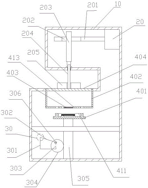
[0016] Embodiment 1 is basically as attached figure 1 Shown: an automatic demoulding device, including a frame 10, a mold body, a first separating device and a second separating device. The mold body includes an upper mold 404, a lower mold 403, a mold body 401 and a mold frame 402. The mold frame 402 is detachably installed in the middle of the frame 10. The shape and size of the upper mold 404 are slightly smaller than the mold frame 402. The upper mold 404 can Slide in the mold frame 402, the lower mold 403 is fixedly connected on the bottom surface of the mold frame 402, the lower mold 403 is provided with a mold groove 413 that runs through the lower mold 403, the mold body 401 is separated from the lower surface of the lower mold 403, and the mold body 401 There is a protrusion 411 opposite to the mold groove 413. The shape of the protrusion 411 is the external shape of the part. Lifting the mold body 401 can make the material in the mold body form the external shape of ...


PUM


Abstract

The invention relates to the field of molds and particularly discloses an automatic demolding device. The automatic demolding device comprises a rack, a mold body, a first separation device and a second separation device. The first separation device of the automatic demolding device is fixedly mounted at the bottom of the rack. The second separation device is fixedly mounted at the top of the rack. The first separation device comprises a threaded rod, a first connecting rod mechanism, a handle, a locating block and a gear, wherein the gear is engaged with the threaded rod. The mold body is detachably connected with the upper end of the threaded rod. The locating block is eccentrically arranged on the side face of the gear. One end of the first connecting rod mechanism is connected with the locating block, and the other end of the first connecting rod mechanism is connected with the handle. The second separation device comprises a separation motor, a transmission shaft and a second connecting rod mechanism. The separation motor is connected with one end of the second connecting rod mechanism, and the other end of the second connecting rod mechanism is connected with one end of the transmission shaft. The other end of the transmission shaft is detachably connected with the upper surface of an upper mold. By means of the automatic demolding device, a pressure-casting mold can be manufactured, and a molding mold can be separated from the mold body automatically.

Description

technical field [0001] The invention belongs to the field of mold casting, and in particular relates to a demoulding device. Background technique [0002] Because the molding materials used in sand casting are cheap and easy to obtain, the casting mold is easy to manufacture, and it can adapt to the single-piece production, batch production and mass production of castings. It has been the basic process in casting production for a long time. At present, in the international production of all castings, 60-70% of the castings are produced by sand casting. Compared with other casting methods, sand casting has low cost, simple production process and short production cycle. [0003] In the manufacturing process of sand molds, each sand mold needs to be processed and shaped separately. First, the casting sand is filled into the mold, and then the casting sand in the mold is pressed to ensure that the casting sand is tightly bonded, and then the mold is taken out. Sand mold, the m...

Claims


Application Information

Patent Timeline
IPC IPC(8): B22C19/06
CPCB22C19/06
Inventor 唐正权
Owner 大冶屹丰机械制造有限公司
Learn More