
Multi-layer feed stirrer

A mixer and feed technology, which is applied to mixer accessories, feed, mixers with rotating stirring devices, etc., can solve the problems of uneven discharge, incomplete, low feed mixing efficiency, etc., to achieve convenient discharge and avoid feed mixing layered effect

Inactive Publication Date: 2017-05-17
西安发威电子科技有限公司
View PDF1 Cites 3 Cited by
  • Summary
  • Abstract
  • Description
  • Claims
  • Application Information

AI Technical Summary

Problems solved by technology

[0004] The purpose of the present invention is to provide a multi-layer feed mixer to solve the problems of low feed mixing efficiency, stratification, unevenness and incomplete discharge in the prior art

Method used


Image

  • Multi-layer feed stirrer
  • Multi-layer feed stirrer
  • Multi-layer feed stirrer

Examples


Embodiment 1

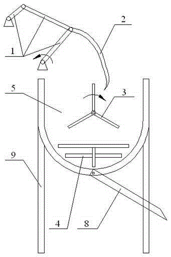
[0017] figure 1 It is a schematic diagram of the front view structure of an embodiment of the present invention. The multi-layer feed mixer includes a frame 9, and the frame 9 is provided with a mixing drum 5; the inside of the mixing drum 5 is respectively provided with The first stirring device 2 , the second stirring device 3 and the third stirring device 4 ; the first stirring device 2 is connected with the crank linkage mechanism 1 .

Embodiment 2

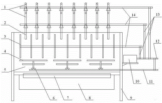
[0019] On the basis of embodiment 1, figure 2 It is a right-view structure schematic diagram of an embodiment of the present invention. The multi-layer feed mixer includes a frame 9, and the frame 9 is provided with a mixing drum 5; the inside of the mixing drum 5 is respectively provided with The first stirring device 2, the second stirring device 3 and the third stirring device 4, the right side of the mixing drum 5 is provided with a motor 10; the first stirring device 2 is connected with the crank linkage mechanism 1, and the crank linkage mechanism 1 is connected With the rotating shaft 14; the second stirring device 3 is directly connected with the rotating shaft 14; the third stirring device 4 is connected with the worm wheel 6, and the worm wheel 6 is connected with the worm; The shaft 14 is connected to the worm 11.

Embodiment 3

[0021] On the basis of embodiment 2, the multi-layer feed mixer includes a frame 9, and the mixing drum 5 is arranged on the frame 9; the inside of the mixing drum 5 is respectively provided with a first stirring device 2 from top to bottom. , the second stirring device 3 and the third stirring device 4, the right side of the mixing drum 5 is provided with a motor 10; the first stirring device 2 is connected to the crank linkage mechanism 1, and the crank linkage mechanism 1 is connected to the rotating shaft 14; The second stirring device 3 is directly connected with the rotating shaft 14; the third stirring device 4 is connected with the worm wheel 6, and the worm wheel 6 is connected with the worm; Connected; the bottom of the mixing drum 5 has a discharge port 7 and is provided with a discharge slide 8, and the discharge is more convenient and thorough.


PUM


Abstract

The present invention belongs to the technical field of agricultural machinery, and more particularly relates to a multi-layer feed stirrer, which comprises a rack, wherein the rack is provided with a stirring cylinder, the interior of the stirring cylinder is respectively provided with a first stirring device, a second stirring device and a third stirring device from top to bottom, the right side of the stirring cylinder is provided with a motor, the bottom portion of the stirring cylinder is provided with a material outlet and is provided with a material outlet slide, the first stirring device is connected to a crank connection rod mechanism, the crank connection rod mechanism is connected to a rotation shaft, the second stirring device is directly connected to the rotation shaft, the third stirring device is connected to a worm wheel, the worm wheel is connected to a worm, and the motor is respectively connected to the rotation shaft and the worm through belts. According to the present invention, the multi-layer feed stirrer has characteristics of simple working principle, easy operation, high stirring efficiency, uniform feed stirring, no feed layering, and convenient and complete material discharging.

Description

technical field [0001] The invention belongs to the technical field of agricultural machinery, and in particular relates to a multi-layer feed mixer. Background technique [0002] Feed mixing is a necessary step for farms. The traditional way of mixing feed is manual mixing. However, this method is time-consuming and laborious, and has low work efficiency. It has been gradually eliminated in large-scale farms and replaced by feed mixers. The current feed mixers are roughly divided into two types, horizontal feed mixers and vertical feed mixers. For example, the application number: 201120444071.2 discloses a mobile small-scale dry and wet feed mixer, which is equipped with a rust-free steel plate mixing tank. The upper part of the mixing tank is cylindrical and the lower part is conical. The inside of the mixing tank is a hollow cylindrical body. Steel plate, the bottom of the barrel has a main mixing knife whose length is the inner diameter of the cylinder, the middle part ...

Claims


Application Information

Patent Timeline
Patent Type & Authority Applications(China)
IPC IPC(8): B01F7/00B01F15/02A23N17/00
Inventor 吴华丽
Owner 西安发威电子科技有限公司
Learn More