
Nut tightening machine

A technology for fastening machines and nuts, applied in the direction of screwdrivers, motor tools, light motorized devices, etc.

Active Publication Date: 2017-05-10
MAKITA CORP
View PDF7 Cites 2 Cited by
  • Summary
  • Abstract
  • Description
  • Claims
  • Application Information

AI Technical Summary

Problems solved by technology

Therefore, unnecessary electric power unrelated to the above-mentioned fastening unnecessarily reduces the power of the limited rechargeable battery, thereby increasing the demand for suppressing such unnecessary electric power consumption.

Method used


Image

  • Nut tightening machine
  • Nut tightening machine
  • Nut tightening machine

Examples


Embodiment Construction

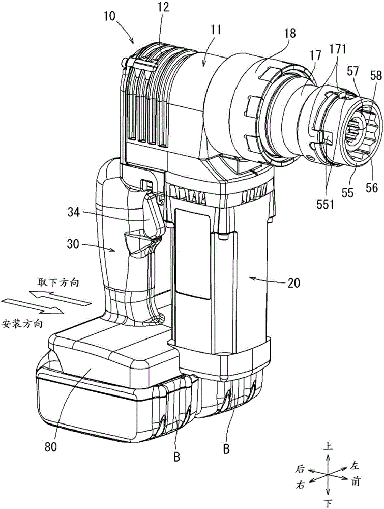
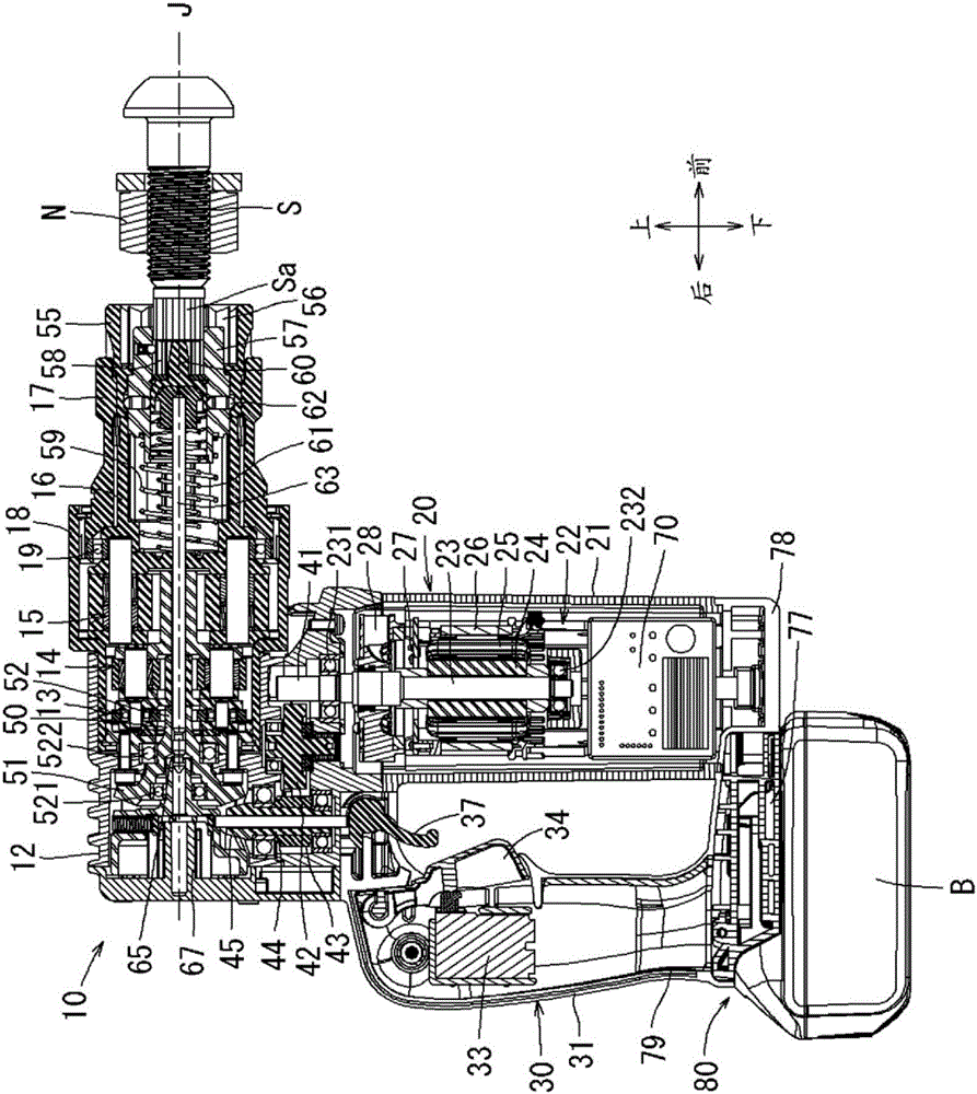
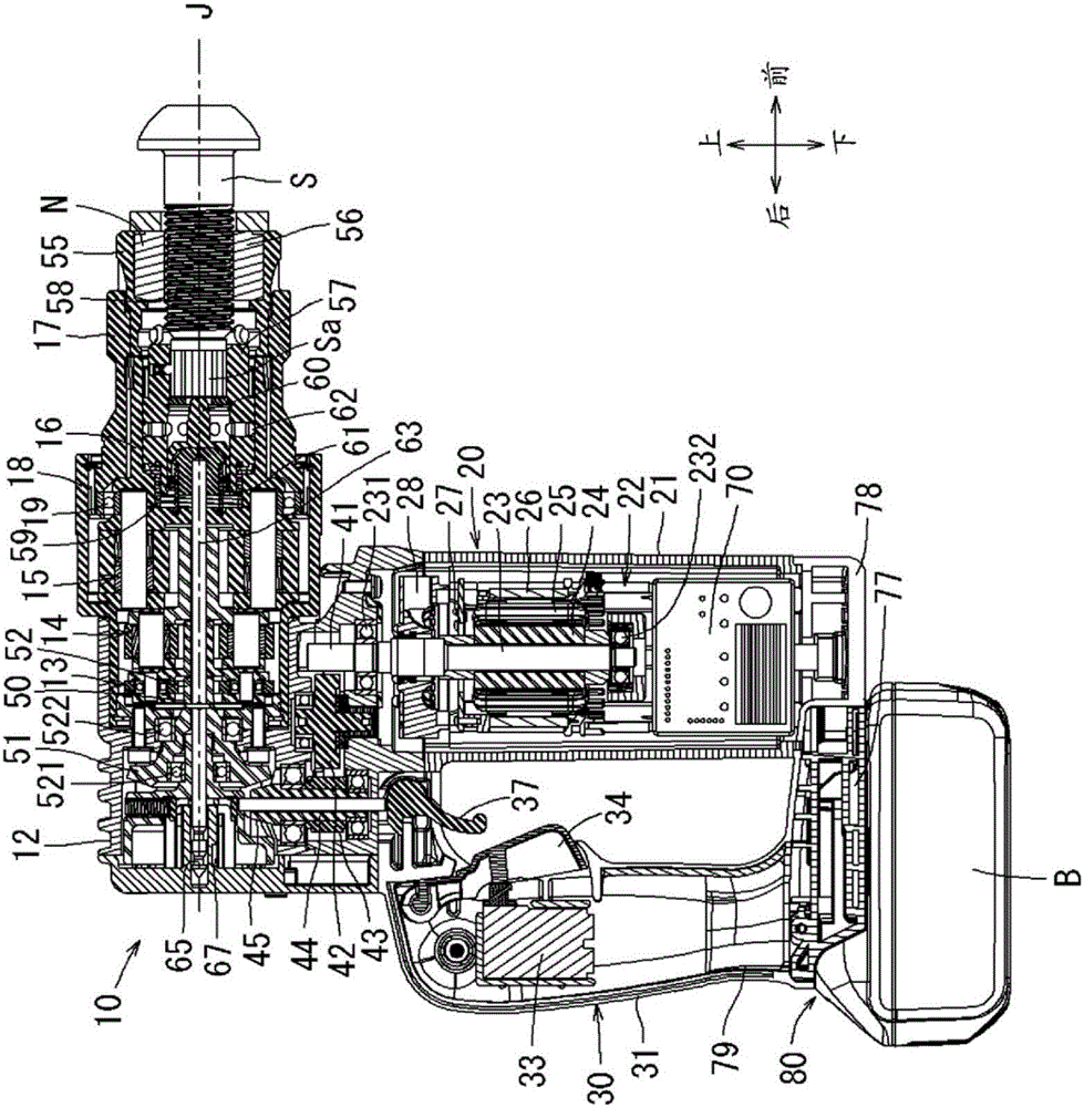
[0024] Hereinafter, an embodiment of a nut tightening machine for carrying out the present invention will be described. figure 1 The perspective view of is three-dimensionally shows the overall appearance of the nut tightening machine 10. figure 2 as well as image 3 The cross-sectional view of FIG. 1 shows the internal construction of the nut tightening machine 10 . also, figure 2 The state before the end portion Sa of the shear bolt S is inserted into the inner socket 57 is shown, image 3 The state where the tip part Sa of the shear bolt S is inserted into the inner socket 57 is shown.

[0025] In addition, when describing the nut tightening machine 10 below, it demonstrates based on the direction of front, back, up, down, left and right described in drawing. The illustrated nutrunner 10 is also a tool called a torsional shear wrench. This nut tightening machine 10 is used for screw-fastening a hexagonal nut N to a shear bolt S. As shown in FIG. In other words, the ...


PUM


Abstract

An operation switch (33) sends an ON signal, indicating to switch ON, to a control processing device (71). A magnetic sensor (67) sends sensor signals to the control processing device (71) on the basis of displacement to the rear side of a tip rod. The control processing device (71) performs first mode control whereby a brushless DC motor (22) is not driven, if no sensor signal has been sent. The control processing device performs second mode control whereby the brushless DC motor (22) is driven, if a sensor signal has been sent. Output in this first mode is lower than the output in the second mode. As a result, power consumption efficiency is improved for power that is supplied when the nut tightening machine is switched on but is not tightening hexagonal nuts, even if a manual ON input by a user remains ON.

Description

technical field [0001] The present invention relates to a nut tightening machine for tightening nuts to bolts. Background technique [0002] In recent years, bolts called torsional shear bolts (hereinafter referred to as "shear bolts") have been used for screw fastening in steel structures. The shear bolt utilizes a nut to complete thread fastening. The screw tightening by this nut is performed by two tightenings of main tightening and final tightening. For tightening such nuts, for example, a nut tightening machine referred to in JP 2009-297858 A is used. In addition, the above-mentioned turning-on operation of the nut tightening machine is performed by the pulling operation of the operation trigger provided on the tool main body. [0003] However, nuts are sometimes continuously fastened to a plurality of shear bolts at construction sites. In such a case, it is troublesome to disconnect the above-mentioned nut tightening machines one by one. That is, when the nuts are...

Claims


Application Information

Patent Timeline
Patent Type & Authority Applications(China)
IPC IPC(8): B25B23/14B25B23/153
CPCB25B21/00B25B23/1415B25B23/147B25F5/001B25F5/02B25B21/008
Inventor 西宫岳志柘植和则古居伸康
Owner MAKITA CORP
Learn More