
Optical device for measuring wavelength and control method thereof

An optical device and wavelength technology, applied in the field of optical prisms, to achieve the effect of convenient use

Pending Publication Date: 2017-05-10
BEIJING JIAHE HENGDE TECH CO LTD
View PDF5 Cites 0 Cited by
  • Summary
  • Abstract
  • Description
  • Claims
  • Application Information

AI Technical Summary

Problems solved by technology

[0004] The main problem solved by the present invention is to provide an optical device and control method for measuring the wavelength to solve the problems of high-precision control of the laser direction and repeated disassembly, maintenance and debugging.

Method used


Image

  • Optical device for measuring wavelength and control method thereof
  • Optical device for measuring wavelength and control method thereof
  • Optical device for measuring wavelength and control method thereof

Examples


Embodiment 1

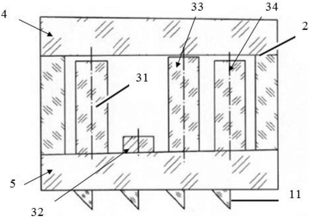
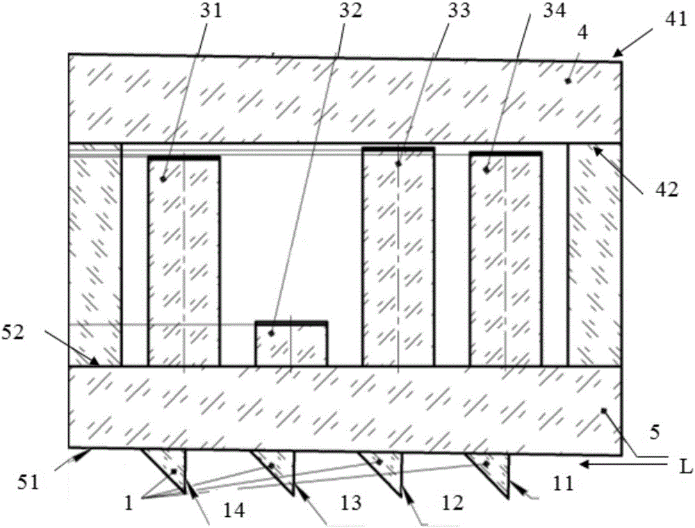
[0024] like figure 1 , figure 2 , Figure 5 , Image 6 A structural diagram of an optical device for measuring wavelengths is provided for an embodiment of the present invention, including a cavity provided with a peripheral wall 2, an upper cover 4 and a lower cover 5, and the lower cover of the cavity is arranged The four prism-shaped prisms 1 are respectively prism 11, prism 12, prism 13, and prism 14, and the prisms corresponding to the prisms arranged inside the cavity and on the inner surface 52 of the lower cover are respectively prism 31, prism 32, prism 33, prism 34. Make the light to be measured pass through the prism 1, the lower cover plate 5, the prism 3 and the upper cover plate 4 to form light rays with only different optical paths for measurement.

[0025] A right-angled surface of the prism 1 is the incident surface of the light L to be measured entering the glass from the air from right to left, and the inclined surface of the prism 1 is the exit surface ...

Embodiment 2

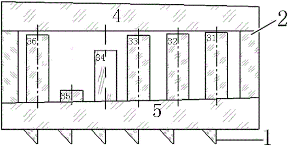
[0033] like image 3 , Figure 4 , Figure 5 A structural schematic diagram of an optical device for measuring wavelengths is provided for an embodiment of the present invention, including a cavity provided with a peripheral wall 2, an upper cover 4 and a lower cover 5, and the lower cover of the cavity is provided with Six prism-shaped prisms 1, respectively prism 11, prism 12, prism 13, prism 14, prism 15, and prism 16, are arranged inside the cavity and on the inner surface 52 of the lower cover corresponding to the prisms. The prisms are respectively prism 31, prism 32, prism 33, prism 34, prism 35, and prism 36, so that the light to be measured is formed after passing through prism 1, lower cover plate 5, prism 3 and the upper cover plate 4. light path for measurement.

[0034] A right-angled surface of the prism 1 is the incident surface of the light L to be measured entering the glass from the air from right to left, and the inclined surface of the prism 1 is the exi...


PUM


Abstract

The invention belongs to the technical field of optical prisms, and particularly relates to an optical device for measuring wavelength. The optical device comprises a cavity provided with a peripheral wall, an upper cover plate and a lower cover plate, at least two prisms in the shape of triangular prisms are arranged on the lower cover plate of the cavity, prismatic columns corresponding to the prisms are arranged inside the cavity and on the inner surface of the lower cover plate, and to-be-measured light is enabled to form light only having different optical paths for measuring after passing the prisms, the lower cover plate, the prismatic columns and the upper cover plate. By the optical device, the problems of high-precision control in laser direction and repeated demounting for maintaining and debugging can be solved. The optical cavity can be applied in high-precision measuring of spectra having pulse laser or continuous laser wavelength and analysis. Precision of the optical cavity in measuring laser wavelength can reach 1X10⁻⁷, and the optical device has the advantage of convenience in use.

Description

technical field [0001] The invention belongs to the technical field of optical prisms, in particular to an optical device for measuring wavelengths and a control method thereof. Background technique [0002] The current device for changing the laser direction has a large precision control error and the control method needs to be repeated many times, especially the optical cavity of its core product is the core optical component of the laser wavelength meter instrument. The wavelength meter is the only instrument that can accurately measure the value of the laser wavelength by means of optical measurement. Products are widely used in scientific research, optical communication and industrial fields. As a whole, the designed wavelength meter and the current optical cavity cannot be used for high-precision measurement of the spectrum and analysis of pulsed laser or continuous laser wavelength. [0003] Therefore, how to develop an optical device for measuring wavelengths, avoi...

Claims


Application Information

Patent Timeline
IPC IPC(8): G01J9/00
CPCG01J9/00
Inventor 周长颖
Owner BEIJING JIAHE HENGDE TECH CO LTD
Learn More