
A column welding device

A welding device and column technology, applied in welding equipment, auxiliary equipment, auxiliary welding equipment, etc., can solve the problems of potential safety hazards, low efficiency, time-consuming and laborious, etc.

Active Publication Date: 2019-04-09
宁波力隆盛世电器有限公司
View PDF6 Cites 0 Cited by
  • Summary
  • Abstract
  • Description
  • Claims
  • Application Information

AI Technical Summary

Problems solved by technology

The existing columns and connecting blocks are respectively clamped and fixed by the clamping device, and are fixed by manual welding. This method has the defects of only processing one column at a time, low efficiency, and unstable welding quality. The welding quality is not good enough to leave safety hazards, which is time-consuming and labor-intensive, requiring more manpower and working hours, and the production cost is higher

Method used


Image

  • A column welding device
  • A column welding device
  • A column welding device

Examples


Embodiment Construction

[0022] The substantive features of the present invention will be further described below in conjunction with the accompanying drawings and specific embodiments.

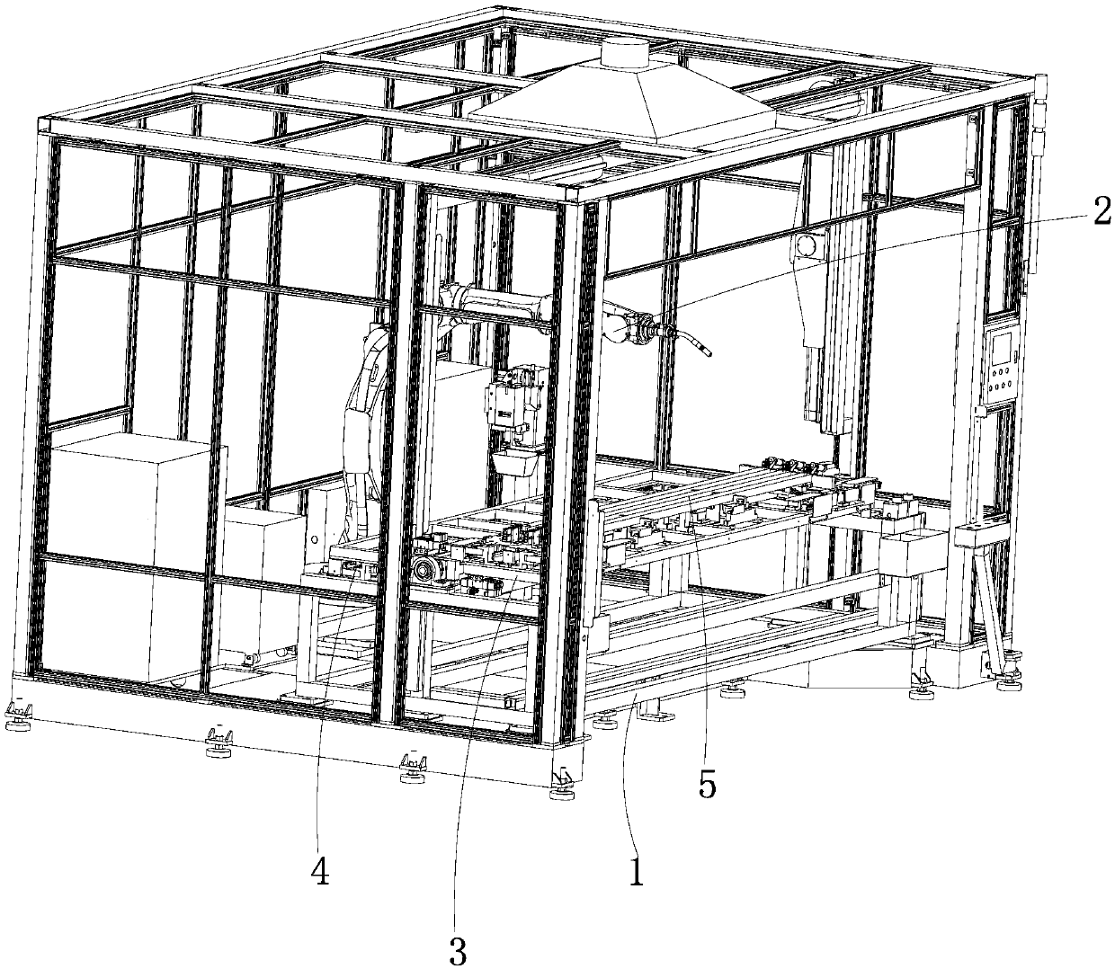
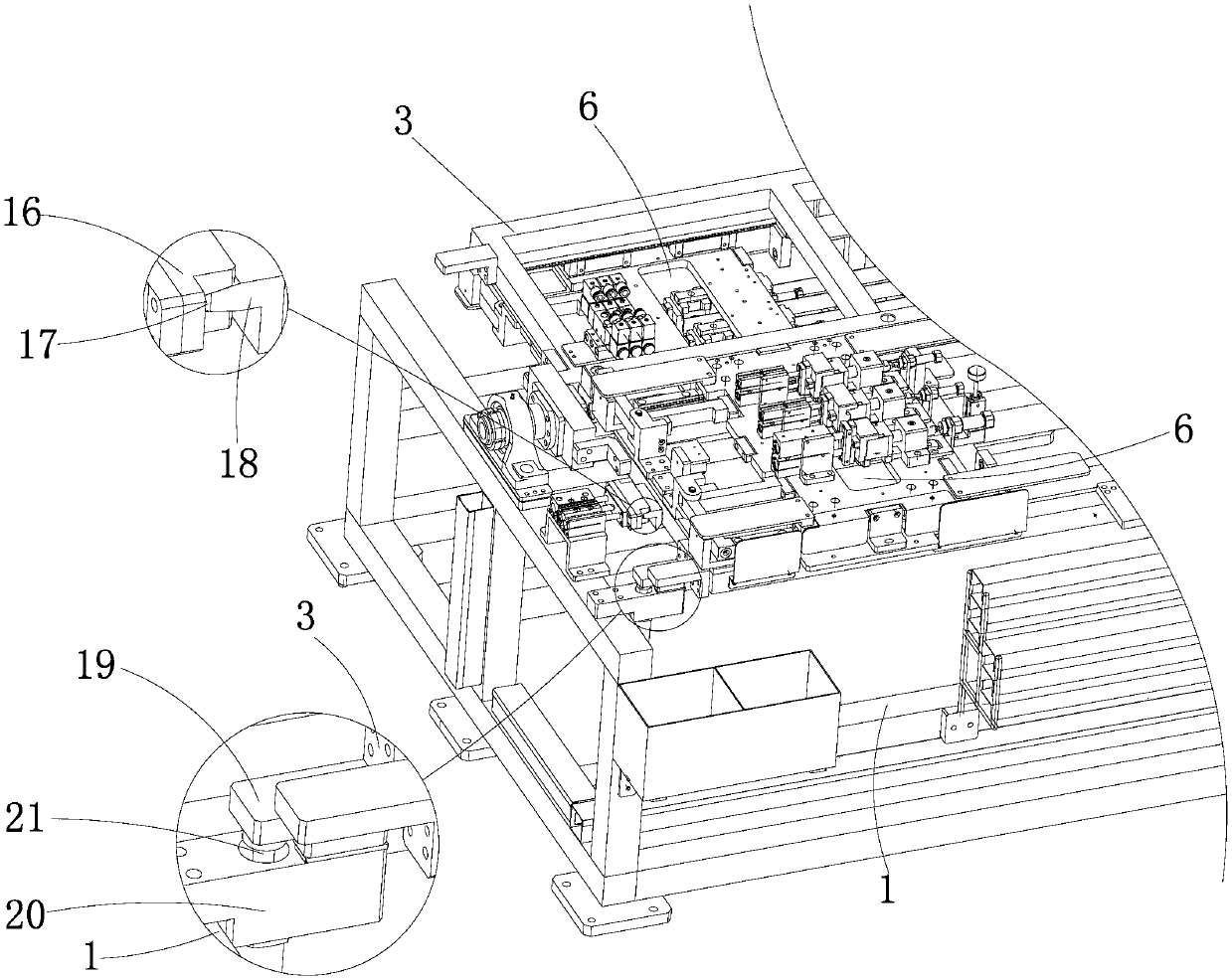
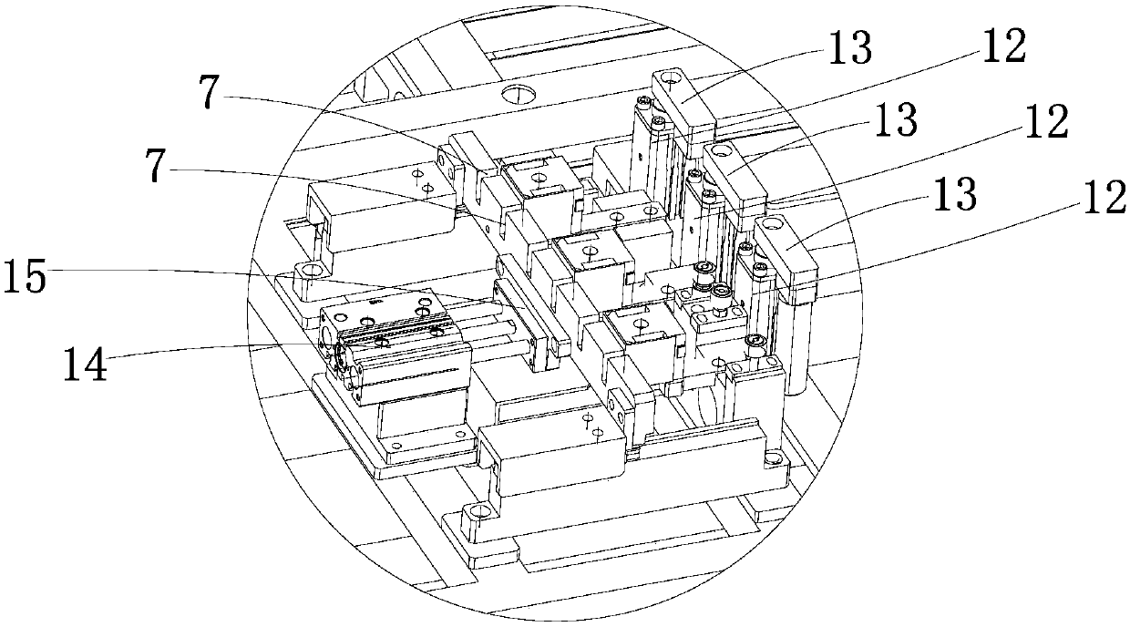
[0023] Such as figure 1 A column welding device shown is composed of a frame 1 and an operating arm 2 arranged on one side of the frame 1 for welding. The top of the frame 1 is rotatably connected to a turning frame 3, and on the turning frame 3 There are two sets of clamping structures arranged symmetrically with the rotation axis of the overturning frame 3, and the reciprocating rotation of the overturning frame 3 makes the two sets of clamping structures in the welding station 4 that cooperates with the operating arm 2 and the material replacement station of the opening and closing clamping structure. 5 switch between.

[0024] Two sets of clamping structures are arranged in an axisymmetric manner on the reciprocating turning frame 3, so that when one set of clamping structures is welded with the operation arm 2,...


PUM


Abstract

The invention relates to a stand column welding device. The current stand columns need to be clamped and fixed one by one and then welded by manpower, which is low in production efficiency. The stand column welding device comprises a rack and an operation arm used for welding arranged at one side of the rack, a roll-over stand is rotatably connected to the upper portion of the rack, the roll-over stand is provided with two sets of clamping structures arranged symmetrically on the basis of a roll-over stand spin axis, and the reciprocatingly rotary roll-over stand makes the two sets of clamping structures switch between a welding post cooperated with the operation arm and a feed replacing post of opening and closing the clamping structures. An original single set of clamping structure is improved into the reciprocatingly rotary roll-over stand, manpower welding is replaced by the operation arm used for welding, so that the welding efficiency is effectively improved, by utilizing the two sets of clamping structures on the roll-over stand to switch between the welding post and the feed replacing post, the two sets of clamping structures cooperate with the operation arm to work circularly and continuously, the continuous welding operation of the operation arm is ensured, and the processing efficiency cannot be influenced because feed on a clamping mechanism needs replacing.

Description

technical field [0001] The invention relates to the field of elevators, in particular to elevator production equipment. Background technique [0002] Van elevators are widely used in high-rise or multi-storey buildings, including shafts and cars that move up and down in the shafts. The car includes a top board, a bottom board, a side board and a column spanning between the top board and the bottom board, and the upright post is fixedly connected with the top board, the bottom board and the side board of the car through a connecting block welded on its side wall. The existing columns and connecting blocks are respectively clamped and fixed by the clamping device, and are fixed by manual welding. This method has the defects of only processing one column at a time, low efficiency, and unstable welding quality. The welding quality is not good enough to leave safety hazards, and it is time-consuming and labor-intensive, requiring more manpower and working hours, and the producti...

Claims


Application Information

Patent Timeline
Patent Type & Authority Patents(China)
IPC IPC(8): B23K37/04B23K37/047
CPCB23K37/04B23K37/0443B23K37/047
Inventor 顾益辉伍鹏傅贵
Owner 宁波力隆盛世电器有限公司
Learn More