
Self-deicing device and anti-icing road system

A technology for ice and snow passages, applied to roads, roads, pavement details, etc., can solve problems such as difficulties in removing ice and snow, and achieve the effects of wide implementation, reduced probability and frequency of traffic accidents, and low management and maintenance costs

Active Publication Date: 2017-04-26
央青卓玛
View PDF5 Cites 2 Cited by
  • Summary
  • Abstract
  • Description
  • Claims
  • Application Information

AI Technical Summary

Problems solved by technology

[0005] The purpose of the present invention is to provide a self-deicing and snow-removing device and an anti-icing road system to solve the technical problem of difficult snow and ice removal in the prior art

Method used


Image

  • Self-deicing device and anti-icing road system
  • Self-deicing device and anti-icing road system
  • Self-deicing device and anti-icing road system

Examples


Embodiment 1

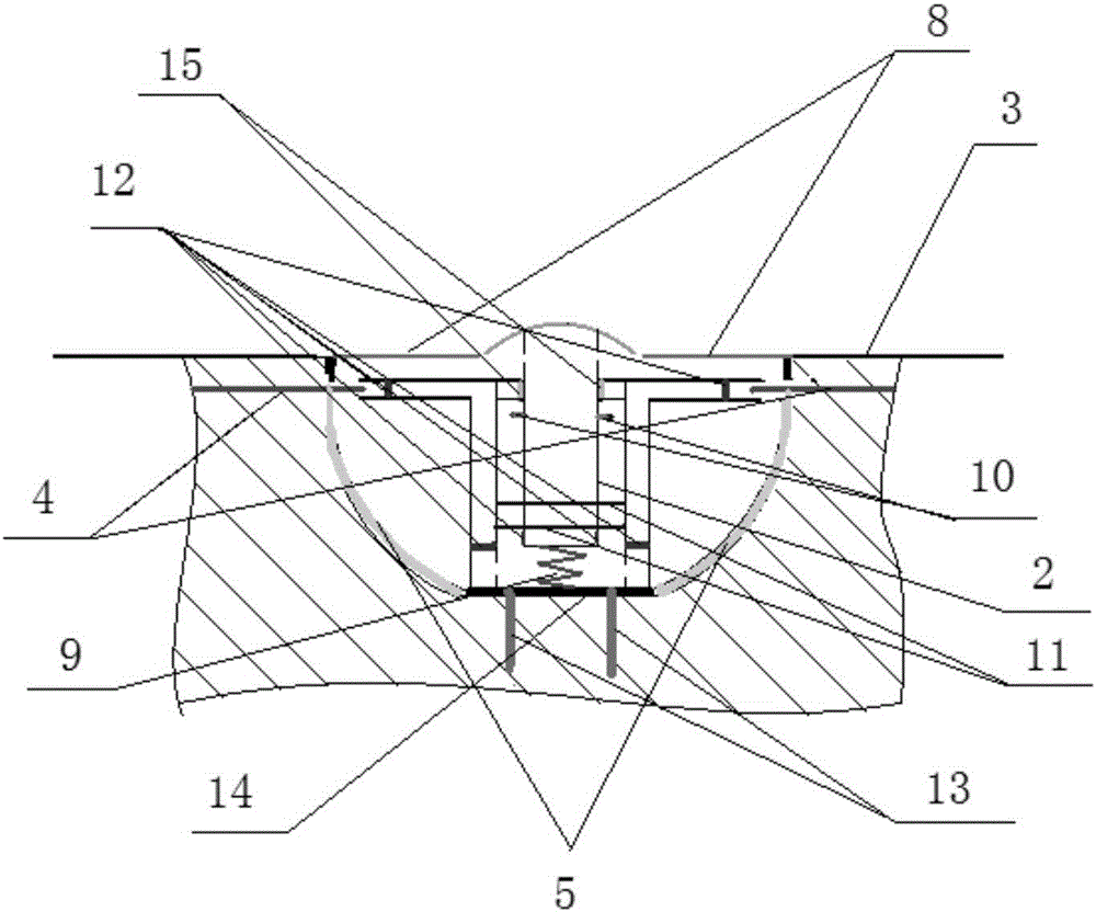
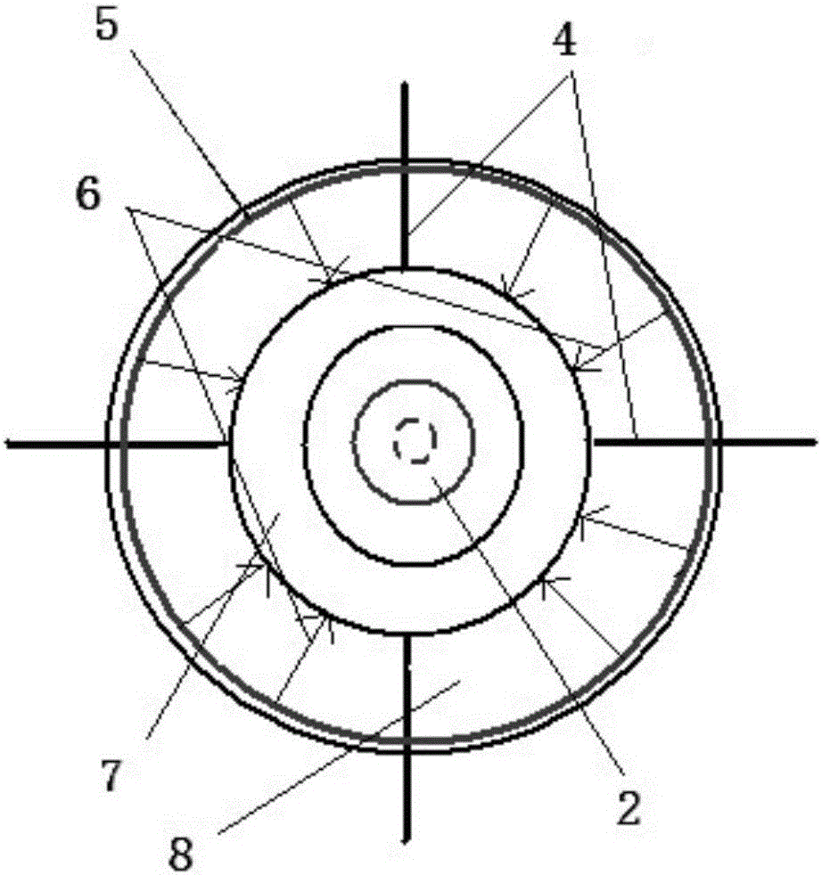
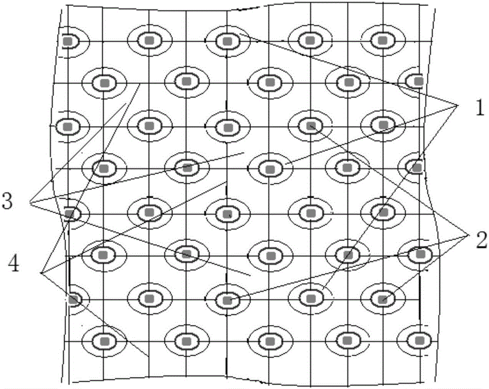
[0041] combine Figure 1 to Figure 3 As shown, the present embodiment provides a self-deicing and snow-removing device, which includes a plurality of energy release honeycombs 1 embedded in the roadbed surface 3 below and a heat dissipation conduit 4 interconnected with the energy release honeycombs 1; the energy release honeycomb 1 includes a nest shell, a transparent glass ring cover 8, and an air compression release device 2; the inner surface of the nest shell is provided with a parabolic mirror 5, of course, the parabolic mirror 5 can be an independent component, or a component integrally connected with the nest shell, There is no limitation here; the compressed air releaser 1 is an independent part that can be detachably connected with the socket, and the compression joint is elastically connected to the bottom, and the shell of the compressed air releaser 1 constitutes the central axis focus column, and the central axis Axis focus column 7 is arranged in the nest shell ...

Embodiment 2

[0057] combine Figure 1 to Figure 3 As shown, the second embodiment also provides an anti-icing road system, which includes the self-deicing and snow removal device in the first embodiment. The self-deicing and snow-removing device includes a plurality of energy release honeycombs 1 embedded in the roadbed surface 3 and a heat dissipation conduit 4 interconnected with the energy release honeycombs 1; the energy release honeycomb 1 includes a nest shell, a transparent glass Ring cover 8, air compression releaser 2; the inner surface of the nest shell is provided with a parabolic mirror 5; the air compression releaser 1 is an independent part that can be detachably connected with the nest shell, wherein the compression joint is elastically connected to the bottom, and The shell of the compressed air releaser 1 constitutes a central axis focal column, and the central axis focal column 7 is arranged in the socket shell along the central axis of the socket shell, and the central a...


PUM


Abstract

The invention relates to the technical field of ice and snow removal and especially relates to a self-deicing device and an anti-icing road system. The self-deicing device comprises multiple energy gathering / releasing honeycombs embedded below a surface of a subgrade and heat radiation conduits connected to the honeycombs, the inner surface of a honeycomb casing of the honeycomb is provided with a parabolic mirror, an air compression releaser is an individual component detachably connected to the honeycomb casing, a compression movable joint is resiliently connected to the bottom, the housing of the air compression releaser forms a central focal column, the central focal column has a central passage and a circumferential passage provided around the central passage, the lower end of the central passage is in communication with the lower end of the circumferential passage, a transparent glass ring cover is packaged at an opening at the upper end of the honeycomb casing, one end of the compression movable join is movably inserted into the central passage of the central focal column, and the one or more heat radiation conduits are connected to the upper opening of the circumferential passage of the central focal column. The self-deicing device has a clever design and is conducive to promotion and application.

Description

technical field [0001] The invention relates to the technical field of deicing and snow removal operations, in particular to a self-deicing and snow removing device and an anti-icing road system. Background technique [0002] With the change of seasons and different locations around the world, there will be frequent snowfall throughout the winter, which will cause damage, paralysis or forced shutdown of regional traffic roads, airports, and even communication, transmission lines and other facilities or equipment. At the same time, snow and ice on roads can easily lead to traffic accidents, which will affect the normal life and economic order of human society and cause economic losses in varying degrees. [0003] In response to this kind of snowfall weather with great influence, the measures currently taken by civil aviation, transportation, electric power and other departments are nothing more than two: one is to strengthen on-site management and guidance; the other is to ca...

Claims


Application Information

Patent Timeline
Patent Type & Authority Applications(China)
IPC IPC(8): E01C11/26
CPCE01C11/265
Inventor 央青卓玛贾皓智刘艳慧
Owner 央青卓玛
Learn More