
Camera focusing method and system

A focusing method and camera technology, applied to parts of TV systems, TVs, and color TVs, etc., can solve problems such as low accuracy of camera focusing operations and limited focusing precision, and achieve improved accuracy and precision, The effect of improving efficiency

Active Publication Date: 2017-03-22
SHENZHEN AUTEL INTELLIGENT AVIATION TECH CO LTD
View PDF4 Cites 9 Cited by
  • Summary
  • Abstract
  • Description
  • Claims
  • Application Information

AI Technical Summary

Problems solved by technology

[0008] The present invention aims to overcome the problems of low accuracy and limited focusing precision of camera focusing operations in the prior art

Method used


Image

  • Camera focusing method and system
  • Camera focusing method and system
  • Camera focusing method and system

Examples


Embodiment 1

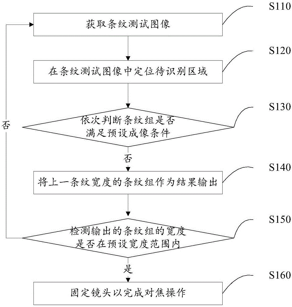
[0033] figure 1 The implementation flow of the camera focusing method provided by the embodiment of the present invention is shown, and the camera focusing method and system are especially implemented as a focusing module or application software in the camera.

[0034] In step S110, a fringe test image is acquired.

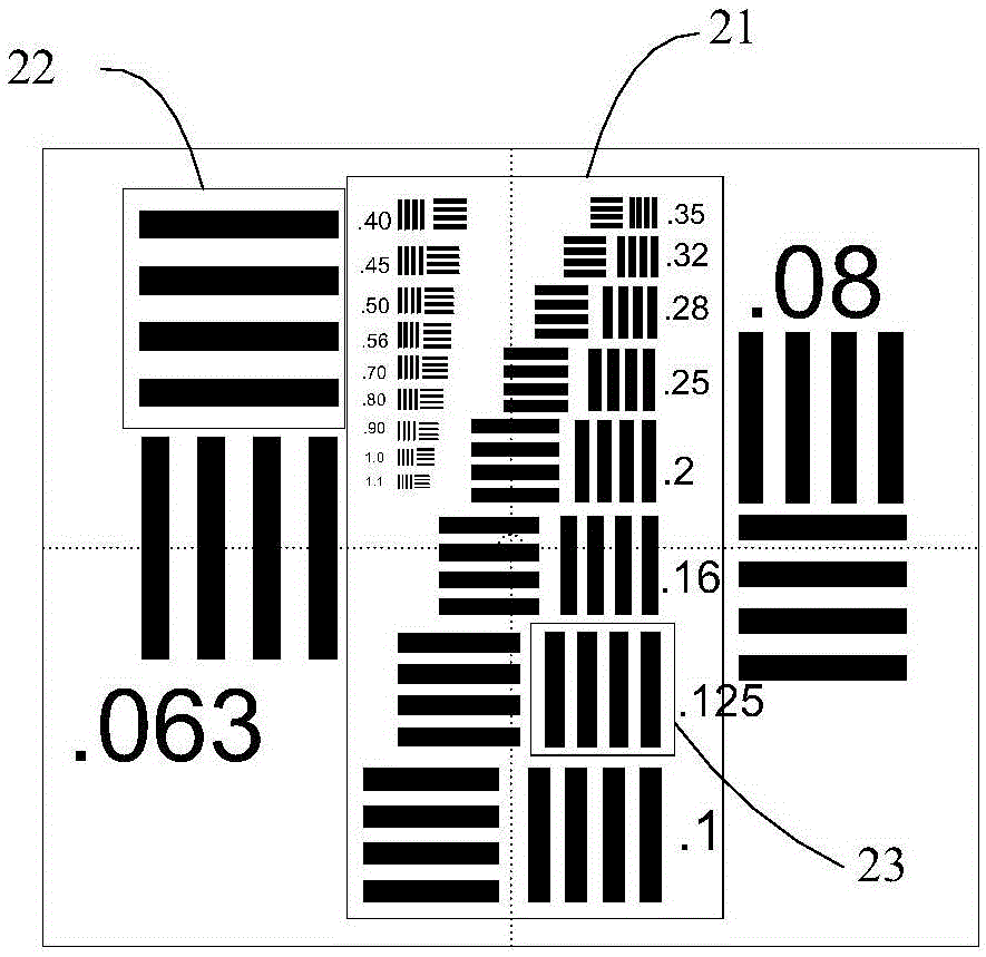
[0035] The streak test image is a test image specially used for focusing operation of a fixed-focus lens. It is currently the most widely used lens focus test image. Specifically, it is as follows: figure 2 shown in the image form. For the convenience of description, the following figure 2 The illustrated image form is taken as an example to illustrate the embodiment of the present invention. The distance between the placement position of the fringe test image and the fixed-focus lens may be the optimal imaging distance corresponding to the focal length of the fixed-focus lens. The fringe test image can be obtained by making a camera use a fixed-focus lens t...

Embodiment 2

[0076] Corresponding to the camera focusing method described in the above embodiment, Image 6 A structural block diagram of the camera focusing system provided by Embodiment 2 of the present invention is shown, and the camera focusing system may be a software unit, a hardware unit or a combination of software and hardware. For ease of description, only the parts related to this embodiment are shown.

[0077] refer to Image 6 , the device consists of:

[0078] An image acquiring unit 61, configured to acquire a fringe test image.

[0079] The positioning unit 62 is configured to locate a region to be recognized in the stripe test image, where the region to be recognized includes a plurality of stripe groups with different stripe widths.

[0080] The judging unit 63 is used to judge whether the stripe group meets the preset imaging condition according to the stripe width from large to small, and if the currently judged stripe group meets the preset imaging condition, then p...


PUM


Abstract

The invention relates to the technical field of cameras, and provides a camera focusing method and system. The camera focusing method comprises the steps that a fringe test image is acquired, and an area to be recognized is positioned in the fringe test image; whether a stripe group satisfies a preset imaging condition is determined according to the stripe width in order from large to small; if the stripe group satisfies the preset imaging condition, the stripe group of next stripe width is judged, otherwise the stripe group of previous stripe width is output as a result; whether the stripe width of the final output stripe group is within a preset stripe width range is detected; and if the stripe width of the final output stripe group is within the preset stripe width range, focus operation is completed, otherwise a lens is adjusted and re-focus operation is carried out. According to the camera focusing method provided by the invention, the accuracy rate and precision of focusing are improved without referring to the observation result of human eyes, and the focusing efficiency is improved.

Description

[0001] 【Technical field】 [0002] The invention relates to the technical field of cameras, in particular to a camera focusing method and system. [0003] 【Background technique】 [0004] Fixed-focus lens, specifically refers to a lens with only one fixed focal length. Compared with zoom lenses, fixed-focus lenses have the advantages of fast focusing speed and stable imaging quality. Therefore, they have played an important role in many fields such as video surveillance, sports cameras and photography creation. role. [0005] In the production process, technicians need to focus on the fixed-focus lens: use the fixed-focus lens to shoot the fringe test image at a certain distance, and judge whether the fixed-focus lens is focused accurately according to whether the details of the fringe test image are clear , if the focus is not accurate, continue to adjust the focal length of the fixed-focus lens until the focus is completed. [0006] However, the above-mentioned focusing proce...

Claims


Application Information

Patent Timeline
IPC IPC(8): H04N5/232
Inventor 李佐广龚煜刘洋
Owner SHENZHEN AUTEL INTELLIGENT AVIATION TECH CO LTD
Learn More