
Straw pulling force tester

A pull-out force and tester technology, applied in the field of force measurement, can solve problems such as inability to pull up vertically, inaccurate pull-out force measurement, etc., to achieve improved grip and adaptability, accurate pull-out force, and simple and convenient operation Effect

Active Publication Date: 2017-03-15
QINGDAO AGRI UNIV
View PDF5 Cites 3 Cited by
  • Summary
  • Abstract
  • Description
  • Claims
  • Application Information

AI Technical Summary

Problems solved by technology

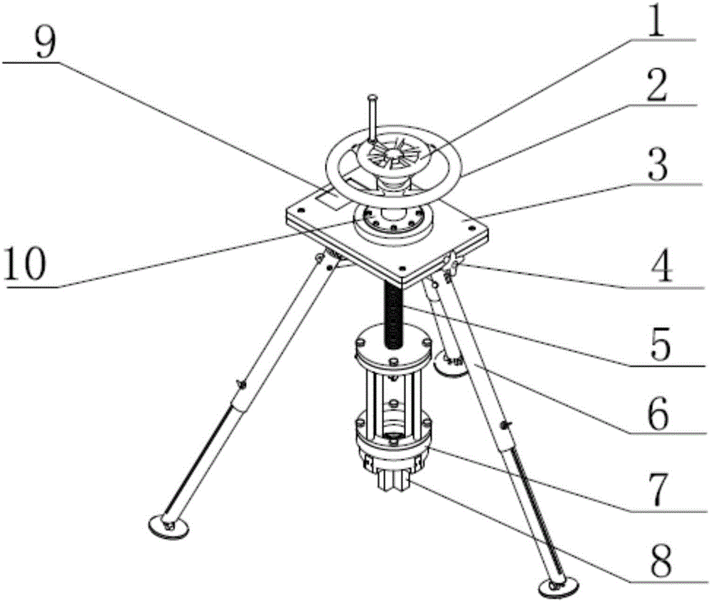
[0005] The purpose of the present invention is to solve the problems in the prior art that cannot be lifted vertically and the measurement of the pulling force is inaccurate, and proposes a straw lifting force tester, which has a simple structure, is easy to operate, and can accurately measure the straw lifting force. pull force

Method used


Image

  • Straw pulling force tester
  • Straw pulling force tester
  • Straw pulling force tester

Examples


Embodiment Construction

[0032] The present invention will be further described below in conjunction with the accompanying drawings and embodiments.

[0033] The straw pulling force tester includes a vertical holding mechanism 10 , a clamping mechanism, a lifting mechanism and a bracket 6 .

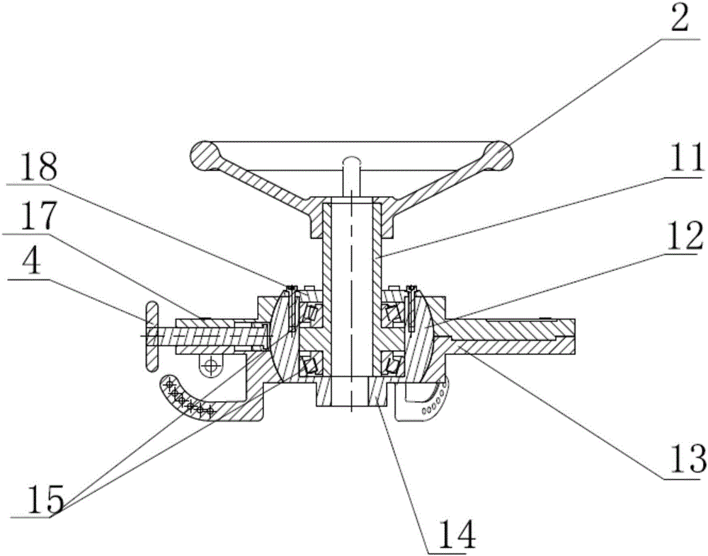
[0034] Such as figure 2 As shown, the vertical holding mechanism 10 includes a workbench 3, a spherical sleeve 12, a spherical sleeve cover 18 and a pressing device 4, wherein the workbench 3 includes an upper part 17 of the workbench and a lower part 13 of the workbench, and the upper part of the workbench 17 is fixed above the lower part 13 of the workbench, and a pressing device 4 is arranged between the upper part 17 of the workbench and the lower part 13 of the workbench. The ball sleeve 12 is arranged at the center of the workbench 3 and is located inside the workbench 3 . The top of the spherical sleeve 12 is fixed with a spherical sleeve cover 18 , and the bottom of the spherical sleeve 12 is provided ...


PUM


Abstract

The invention relates to the technical field of force measurement, especially a straw pulling force tester. The tester comprises a vertical maintaining mechanism, a clamping mechanism, a lifting mechanism, and a support. The vertical maintaining mechanism comprises a workbench, a spherical sleeve, and a compression device. The spherical sleeve is disposed at the center of the workbench, and is located in the workbench. The bottom of the spherical sleeve is fixedly provided with a rectangular projection, and the interior of the inner cavity of the spherical sleeve is provided with a lifting mechanism. The external surface of the spherical sleeve is spherical, and cooperates with the workbench. The spherical sleeve rotates in the workbench, and enables the lifting mechanism and the clamping mechanism to remain vertical under the action of gravity. One end of the compression device is spherical, and contacts with the spherical sleeve. The lifting mechanism comprises a pulling hand wheel, a threaded sleeve, a pulling rod, and a strain-type pulling force sensor. The center of the pulling rod is provided with a cavity, and the bottom of the pulling rod is fixedly connected with the clamping mechanism. The tester is simple in structure, is convenient to operate, and can precisely measure the pulling force of straw.

Description

technical field [0001] The invention relates to the technical field of measuring force, in particular to a straw pulling force tester. Background technique [0002] With the development of the rural economy in recent years, most areas implement no-tillage and less tillage for straw crops, reduce tillage as much as possible, and cover the surface with corn and other crop straws, thereby reducing wind and water bites, and improving soil fertility and cold resistance. For this crop treatment method, seeders and tillage machines with stubble handling capabilities, as well as stubble removal equipment, have been produced. [0003] When studying the straw extraction device or harvesting device and the physical and mechanical properties of the straw, it is necessary to measure the binding force between the straw and the soil and the required pulling force, but the mechanical properties of the stem are due to the soil environment and the growth state of the crop. There is a big di...

Claims


Application Information

Patent Timeline
Patent Type & Authority Applications(China)
IPC IPC(8): G01L5/00
CPCG01L5/00
Inventor 王方艳
Owner QINGDAO AGRI UNIV
Learn More