Roller-adjustable multipurpose winding device

A winding device and adjustable technology, applied in the field of roller adjustable multi-purpose winding device, can solve the problems of limited scope of application, troublesome use, low efficiency, etc., and achieve the effects of simple operation, convenient and effective winding

Active Publication Date: 2017-03-15
SHANGHE COUNTY POWER SUPPLY CO STATE GRID SHANDONG ELECTRIC POWER CO +1
View PDF6 Cites 6 Cited by
  • Summary
  • Abstract
  • Description
  • Claims
  • Application Information

AI Technical Summary

Problems solved by technology

[0002] In order to facilitate the storage of longer wires or to wind the wires into specific shapes for use, winding is required. In the prior art, manual winding is generally used, and the efficiency is low; with the development of technology, there are also Some special winders have been developed for winding enameled wires and other wires, but the existing winders use fixed rollers for winding, and can only wind wires of a fixed type or length, and the scope of application is very limited.
[0003] Since the rollers in the winder are fixed, one type of winder can only wind one type of wire, which is easy to occur when the type of the winder and the wire do not match, which leads to When winding wires of different lengths or thicknesses, different wire winders need to be used, which is very troublesome to use. Therefore, we need a winding device that can wind different types of wires.

Method used


Image

  • Roller-adjustable multipurpose winding device
  • Roller-adjustable multipurpose winding device
  • Roller-adjustable multipurpose winding device

Examples


Embodiment Construction

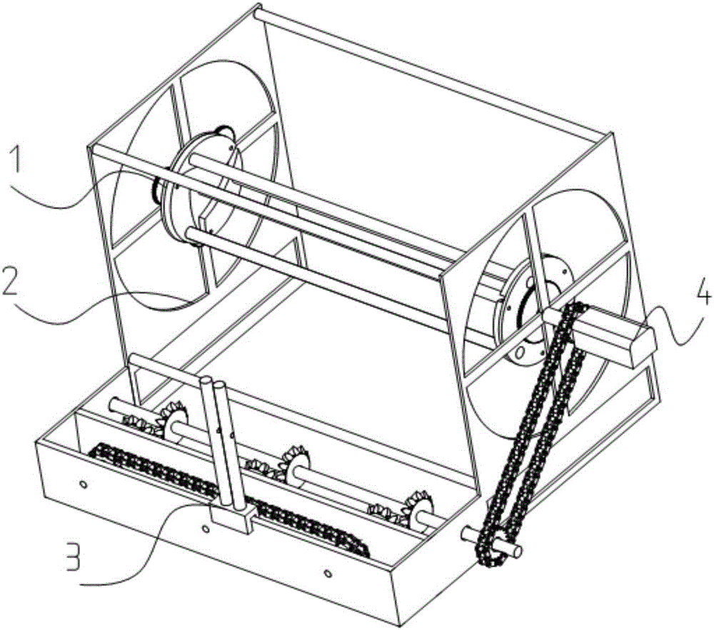
[0031] Such as Figure 1 to Figure 13 Shown is a roller adjustable multi-purpose winding device, the present invention includes a bracket 2, a roller adjusting device 1 and a motor 4, and the present invention will be described below with reference to the accompanying drawings.

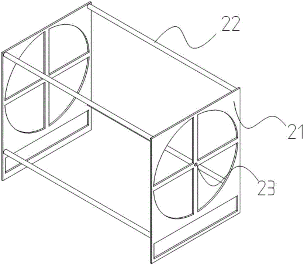
[0032] Such as figure 2 As shown, the support 2 includes a support support plate 21, a cross bar 22 and a central axis hole 23, the support support plate 21 is two vertical plates parallel to each other, the support support plate 21 is set as a Tian-shaped frame, and the middle part of the vertical plate is provided with Central shaft hole 23, cross bar 22 are set as four horizontal long bars, and the two ends of four cross bars 22 are respectively fixed on the four corners of two bracket support plates 21, and cross bar 22 is parallel to each other, and support support plate 21 lower ends Equipped with universal wheels;

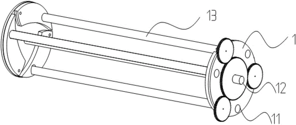
[0033] Such as image 3 As shown, the roller adjustment device 1 is located...


PUM


Abstract

A roller-adjustable multipurpose winding device comprises a bracket, a roller adjusting device and a motor. The bracket comprises bracket supporting boards and transverse rods, wherein the bracket supporting boards are two parallel vertical boards, the transverse rods are four transverse long rods, one ends of the four transverse rods are fixedly arranged at the four corners of one of the bracket supporting boards correspondingly, and the other ends of the four transverse rods are fixedly arranged at the four corners of the other bracket support board correspondingly. The roller adjusting device is arranged in the bracket and comprises two adjusting device bodies, a center shaft and a movable shaft. The two adjusting device bodies are arranged beside the two bracket supporting boards correspondingly. Each adjusting device comprises a rotating plate, a movable block, a driven gear, a movable shaft hole and a driving gear. The center shaft is a long rod, the two ends of the center shaft penetrate through the two adjusting device bodies and are arranged in center shaft holes in the bracket separately, and the motor is arranged at one end of the center shaft. Three movable rods are used for replacing traditional rollers, the positions of the movable rods are changed by rotating the driving gear, then the diameter of the roller is changed, different wires can be wound by changing the diameters of the rollers, and operation is easy.

Description

technical field [0001] The invention relates to the field of wire gathering devices, in particular to a multi-purpose winding device with adjustable rollers. Background technique [0002] In order to facilitate the storage of longer wires or to wind the wires into specific shapes for use, winding is required. In the prior art, manual winding is generally used, and the efficiency is low; with the development of technology, there are also Some special winders have been developed for the winding of enameled wires and other wires, but the existing winders use fixed rollers for winding, and can only wind wires of a fixed type or length, and their scope of application is very limited. [0003] Since the rollers in the winder are fixed, one type of winder can only wind one type of wire, which is easy to occur when the type of the winder and the wire do not match, which leads to When winding wires of different lengths or thicknesses, different wire winders need to be used, which is...

Claims


Application Information

Patent Timeline
IPC IPC(8): B65H54/28B65H75/24
CPCB65H54/28B65H54/2848B65H2701/34
Inventor 王和峰张成贞
Owner SHANGHE COUNTY POWER SUPPLY CO STATE GRID SHANDONG ELECTRIC POWER CO
Why Eureka
Try Eureka