Design method of radio frequency cavity device and its cover plate and cover plate

A design method and technology of radio frequency cavity, which can be applied to waveguide-type devices, electrical components, circuits, etc., and can solve problems such as affecting the performance parameters of radio frequency cavity devices, reducing the reliability of radio frequency cavity devices, affecting passive intermodulation and power capacity, etc. , to achieve the effect of improving the level of passive intermodulation, reducing assembly and debugging man-hours, and reducing the risk of power ignition

Active Publication Date: 2020-07-28
COMBA TELECOM TECH (GUANGZHOU) CO LTD
View PDF5 Cites 0 Cited by
  • Summary
  • Abstract
  • Description
  • Claims
  • Application Information

AI Technical Summary

Problems solved by technology

[0004] However, the metal debris generated during frequent debugging, as well as the thread on the screw and the degree of nut locking, etc., will directly or indirectly affect passive intermodulation and power capacity, and reduce the reliability of RF cavity devices
In addition, if there are too many tuning screws on the cover, the production process and the transportation and movement process may cause the tuning screws to loosen, which will cause changes in the performance parameters of the RF cavity device, and the assembly and debugging will take a long time
It can be seen that the existing technical solutions affect the performance parameters of radio frequency cavity devices, the production efficiency is low, and the production cost is high

Method used


Image

  • Design method of radio frequency cavity device and its cover plate and cover plate
  • Design method of radio frequency cavity device and its cover plate and cover plate
  • Design method of radio frequency cavity device and its cover plate and cover plate

Examples


Embodiment Construction

[0035] Embodiments of the present invention are described in detail below, examples of which are shown in the drawings, wherein the same or similar reference numerals designate the same or similar elements or elements having the same or similar functions throughout. The embodiments described below by referring to the figures are exemplary only for explaining the present invention and should not be construed as limiting the present invention.

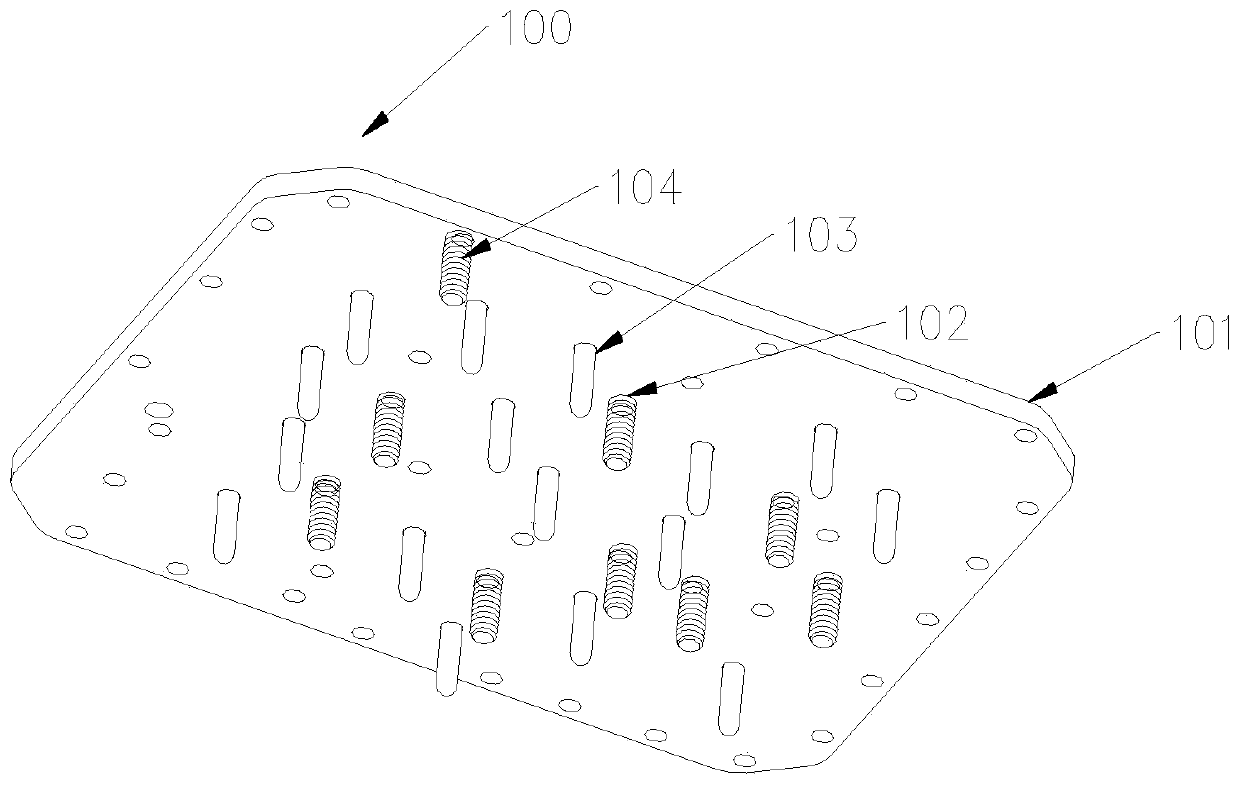
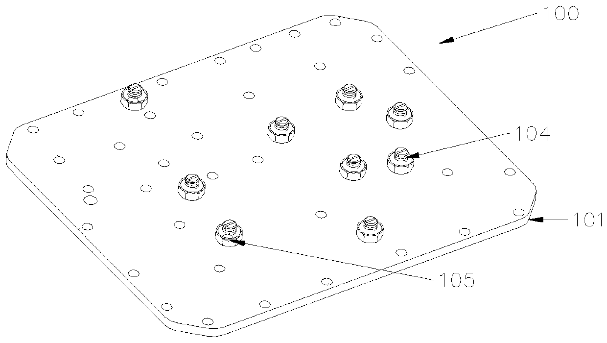
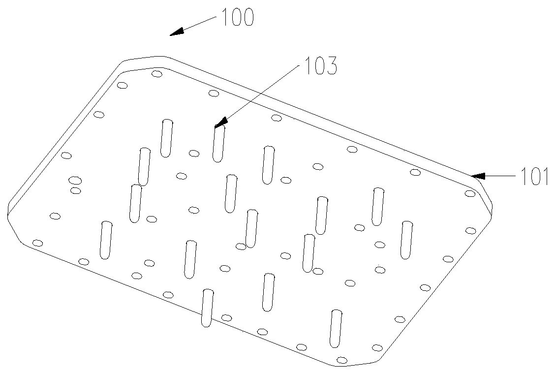
[0036] see figure 1 and figure 2 As shown, the present invention provides a radio frequency cavity device cover plate 100, the radio frequency cavity device cover plate 100 includes a plate body 101, a number of fixed coupling rods 103 extending from the lower surface of the plate body 101 and a number of fixed coupling rods 103 passing through the plate The tuning screw hole 102 on the body 101 goes deep into the threaded adjustable tuning screw 104 on the lower surface of the plate body 101 .

[0037] Specifically, the fixed couplin...


PUM


Abstract

The invention provides a radio frequency cavity device and a cover plate and a design method of the cover plate thereof. The cover plate comprises a plate body, multiple nonadjustable fixed coupling rods which are fixed on the lower surface of the plate body and multiple screwed adjustable tuning screw rods which penetrate into the lower surface of the plate body through tuning screw rod holes arranged on the plate body. According to the radio frequency cavity device and the cover plate thereof, assembling and debugging time can be reduced in screw rod installation and adjustment so that the production efficiency can be enhanced; and metal debris can be reduced and the passive intermodulation level and the power capacity can be enhanced. According to the radio frequency cavity device and the cover plate and the design method of the cover plate thereof, the production cost is low, the filter weight can be reduced, and connection of an active circuit board and a filter is facilitated when it is required so as to form an active and passive integrated module and extend the function of the filter.

Description

technical field [0001] The invention relates to the field of mobile communication, in particular to a radio frequency cavity device, its cover plate and a design method for the cover plate. Background technique [0002] Currently, radio frequency cavity devices (eg, coaxial cavity filters) are widely used in mobile communication systems. In order to make up for processing and assembly tolerances, tuning screws are used for debugging to achieve excellent technical indicators. [0003] When the existing technical solution uses the tuning screw for debugging, it is necessary to open a threaded hole at the corresponding position on the cover plate and use a nut to lock the screw. By rotating the tuning screw to adjust the length of its penetration into the cavity, the cavity filter can be adjusted. performance. [0004] However, the metal debris generated during frequent debugging, as well as the thread on the screw and the degree of nut locking, etc., will directly or indirec...

Claims


Application Information

Patent Timeline
Patent Type & Authority Patents(China)
IPC IPC(8): H01P1/207H01P1/00
CPCH01P1/00H01P1/207
Inventor 孙善球郭春波
Owner COMBA TELECOM TECH (GUANGZHOU) CO LTD
Why Eureka
Try Eureka