
Winding method of transformer coil

A transformer coil and winding method technology, applied in the field of transformers, can solve the problems of manual correction, such as difficulty in improving efficiency, difficulty in meeting requirements, and poor forming effect, so as to prevent leakage of fluid insulating materials, good forming effect, and high work efficiency. Effect

Inactive Publication Date: 2017-02-22
WUHU JINNIU ELECTRIC
View PDF7 Cites 0 Cited by
  • Summary
  • Abstract
  • Description
  • Claims
  • Application Information

AI Technical Summary

Problems solved by technology

[0004] 1. The forming effect is poor, even if it is corrected, it is difficult to meet the requirements;
[0005] 2. Low work efficiency, manual correction is difficult to improve efficiency

Method used


Image

  • Winding method of transformer coil
  • Winding method of transformer coil
  • Winding method of transformer coil

Examples


Embodiment 1

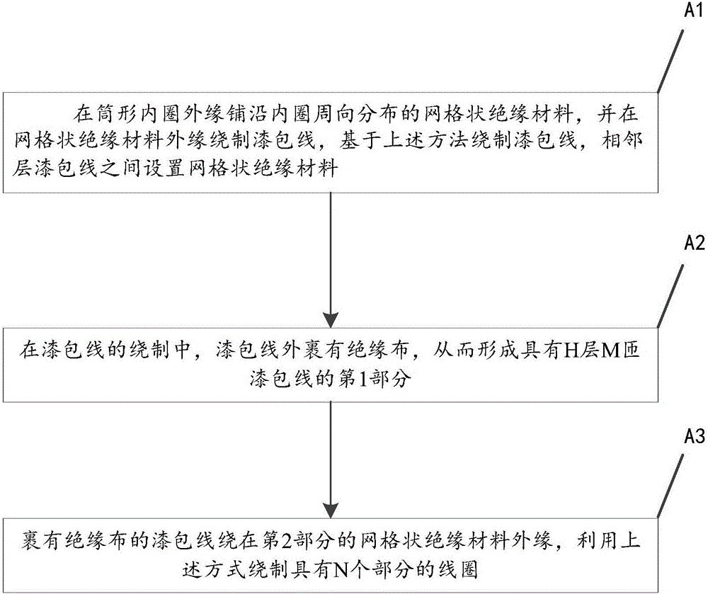
[0042] figure 1 A flow chart of a method for winding a transformer coil according to an embodiment of the present invention is schematically provided, as figure 1 As shown, the winding method of the transformer coil includes the following steps:

[0043] (A1) Lay a grid insulating material distributed along the circumferential direction of the inner ring on the outer edge of the cylindrical inner ring, and wind M turns of enameled wire on the outer edge of the grid insulating material, where M is a positive integer;

[0044] Winding (H-1) layers of enameled wires based on the above method, a grid-shaped insulating material is arranged between adjacent layers of enameled wires, and H is a positive integer;

[0045] (A2) In the winding of the enameled wire with the Mth turn of the H layer, the enameled wire is wrapped with an insulating cloth, thereby forming the first part with the H layer and M turns of the enameled wire;

[0046] (A3) The enameled wire wrapped with insulati...

Embodiment 2

[0048] An application example of the winding method according to Embodiment 1 of the present invention in the manufacture of dry-type transformer coils.

[0049] In this application example, the winding method of the transformer coil includes the following steps:

[0050] (A1) Lay a grid-shaped insulating material distributed along the circumferential direction of the inner ring on the outer edge of the cylindrical inner ring, and wind M turns of enameled wire on the outer edge of the grid-shaped insulating material;

[0051] Winding (H-1) layers of enameled wires based on the above method, and a grid-shaped insulating material is arranged between adjacent layers of enameled wires;

[0052] (A2) In the winding of the enameled wire with the Mth turn of the H layer, the enameled wire is wrapped with an insulating cloth, thereby forming the first part with the H layer and M turns of the enameled wire;

[0053] (A3) The enameled wire wrapped with insulating cloth is wound on the ...


PUM


Abstract

The invention provides a winding method of a transformer coil. The winding method comprises the following steps of (A1) laying a grid-shaped insulating material which is distributed along the circumferential direction of a cylinder inner ring on the edge of the cylindrical inner ring, winding M turns of enamelled wires on the edge of the grid-shaped insulating material, winding (H-1) layers of enamelled wires on the basis of the method and arranging the grid-shaped insulating material between the adjacent layers of enamelled wires; (A2) coating the enamelled wires with insulating cloth during winding of the Hth layer and Mth turn of enamelled wire, thereby forming a first part with H layers and M turns of enamelled wires; and (A3) winding the enamelled wires coated with the insulating cloth on the edge of the grid-shaped insulating material of a second part and winding the coil with N parts by using the methods in the steps (A1) to (A2). The winding has the advantages that the cost is low and the working performance of a transformer is good.

Description

technical field [0001] The invention relates to a transformer, in particular to a winding method of a transformer coil. Background technique [0002] Power transformers are one of the main equipment in power plants and substations. The role of the transformer is multifaceted. It can not only increase the voltage to send electric energy to the power consumption area, but also reduce the voltage to the voltage used at all levels to meet the needs of power consumption. [0003] A power transformer includes an iron core and its outer low-voltage coils and high-voltage coils. Due to human factors in the winding process, the inner and outer sides of the wound coil are not standard arcs or planes, which need to be corrected to improve work performance. The usual practice is to use a hammer to hit the outer coils to make them meet the requirements. This method has disadvantages: [0004] 1. The forming effect is poor, even if it is corrected, it is difficult to meet the requirem...

Claims


Application Information

Patent Timeline
Patent Type & Authority Applications(China)
IPC IPC(8): H01F41/066H01F41/12H01F41/082
CPCH01F41/127
Inventor 刘朝振彭益峰冯俊肖吕斌赵庭福
Owner WUHU JINNIU ELECTRIC
Learn More