
A device for arranging gaps in material shifting rods and grinding gaps

A technology of breaking grinding and feeding rod, which is used in grinding/polishing equipment, metal processing equipment, grinding machines, etc., can solve the problems of inability to achieve automatic arrangement, unstable operation, complex structure of break grinding equipment, etc. Stable and reliable effect, improved rotation effect, high quality and high-efficiency grinding effect

Active Publication Date: 2019-08-20
滨州市科创孵化器有限公司
View PDF5 Cites 0 Cited by
  • Summary
  • Abstract
  • Description
  • Claims
  • Application Information

AI Technical Summary

Problems solved by technology

[0004] One of the purposes of the present invention is to address the deficiencies of the prior art, and overcome the problems in the prior art that the piston ring cannot be automatically arranged after the hole is broken, and the equipment for grinding the hole has a complex structure and unstable operation

Method used


Image

  • A device for arranging gaps in material shifting rods and grinding gaps
  • A device for arranging gaps in material shifting rods and grinding gaps
  • A device for arranging gaps in material shifting rods and grinding gaps

Examples


Embodiment

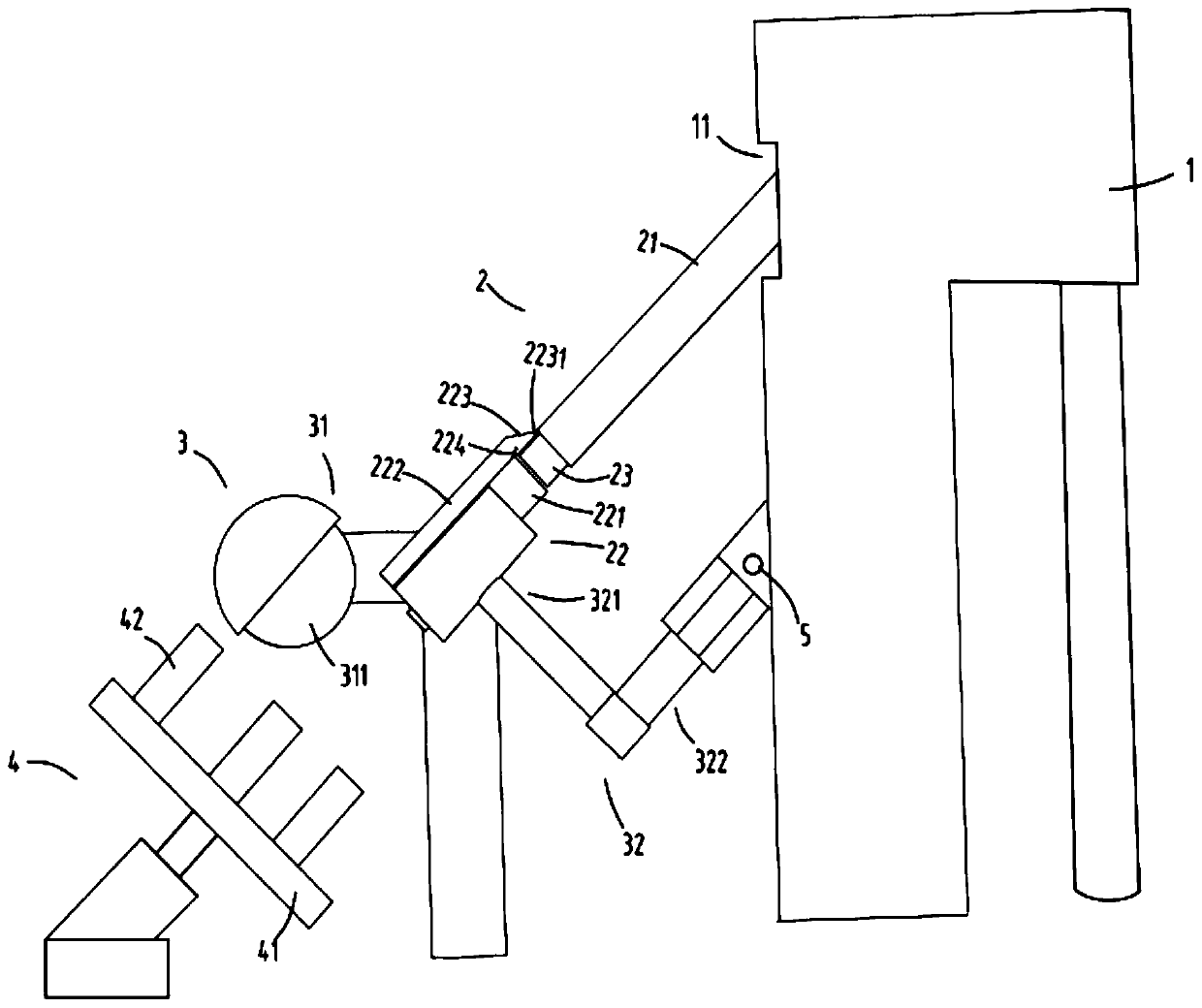
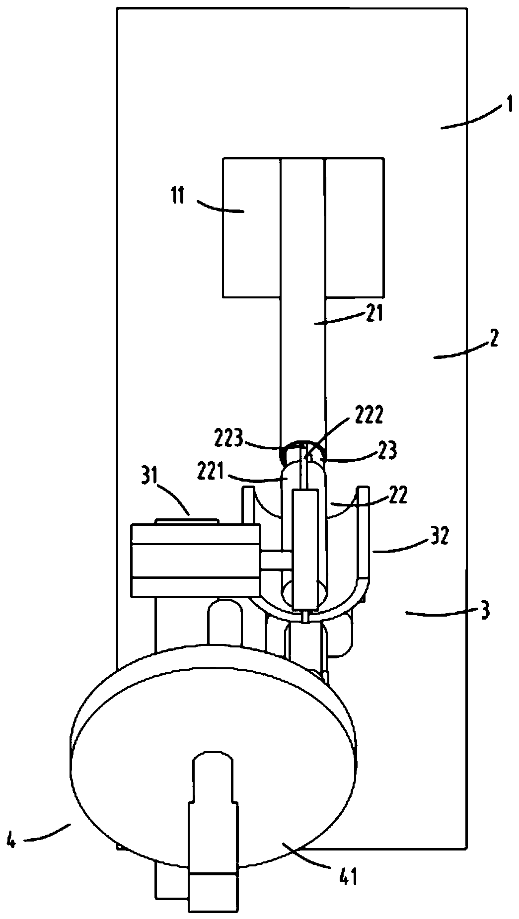
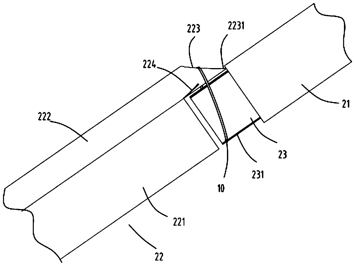
[0027] figure 1 It is a schematic diagram of front view of a device for arranging a hole in a material lever and grinding a hole, figure 2 It is a top view schematic diagram of a device for arranging a break in a material lever and a break grinding device, image 3 It is a schematic diagram of a partial side view of an automatic arrangement device for arranging the breaks of the material lever and the break grinding equipment, Figure 4 It is a structural schematic diagram of an automatic arrangement device for arranging the breaks of the material lever and the break grinding equipment. Such as figure 1 , figure 2 , image 3 and Figure 4 As shown, a device for arranging the break and grinding the break of a material rod includes a breaker 1, an automatic arrangement device 2, a grinding device 3 and a collecting tray 4; The outlet 11 is used to arrange the broken piston rings 10 neatly in a line at the broken place; the grinding device 3 is arranged at the rear end of...


PUM


Abstract

The invention relates to poking rod arrangement cleavage and cleavage polishing equipment. The equipment comprises a cleavage machine, an automatic arrangement device, a polishing device and a collecting disc; the automatic arrangement device is arranged in a material port of the cleavage machine for horizontally and tidily arranging cleaved piston rings according to cleavage places; the polishing device is arranged at the back end of the automatic arrangement device for polishing the cleavage places of the tidily arranged piston rings; the collecting disc is arranged at the back end of the polishing device for collecting the polished piston rings; and the automatic arrangement device includes a blanking rod, an arrangement material rod, and a poking rod arranged between the blanking rod and the arrangement material rod and capable of rotating. The poking rod arrangement cleavage and cleavage polishing equipment overcomes the problems of incapability of realizing automatic arrangement of the cleaved piston rings in the prior art and complex structure and unstable operation of cleavage and polishing equipment.

Description

technical field [0001] The invention relates to the technical field of piston ring production equipment, in particular to equipment for arranging gaps in material shifting rods and grinding the gaps. Background technique [0002] In the production process of piston rings, there are two processes of breaking the ring and then grinding the break; in the prior art, the ring is usually broken on the breaking machine, and then the worker will break the broken piston The rings are polished, and some are manually polished one by one. The quality of the polished piston rings is better, but the efficiency is low and the labor cost is high. Some equipment that can realize automatic grinding generally requires manual arrangement of the piston rings according to the gaps and then loading. For grinding, the worker needs to stand aside and constantly adjust the position of the gap, which is more troublesome to operate, and the gap grinding of the piston ring is also polished one by one by...

Claims


Application Information

Patent Timeline
Patent Type & Authority Patents(China)
IPC IPC(8): B24B19/11B24B41/00B24B41/06
Inventor 丁震华
Owner 滨州市科创孵化器有限公司
Learn More