Method and device for detecting lens stain
A technology for detecting lenses and stains, applied in image data processing, television, instruments, etc., can solve the problems of low accuracy and efficiency
- Summary
- Abstract
- Description
- Claims
- Application Information
AI Technical Summary
Problems solved by technology
Method used
Image

Examples
Embodiment 1
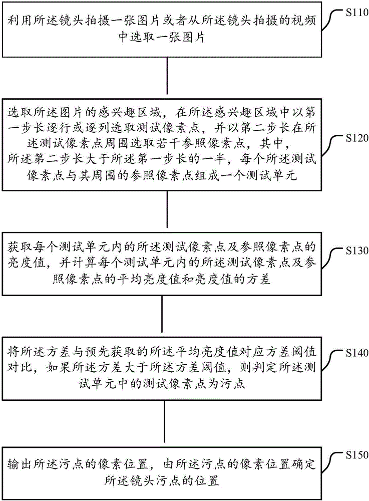
[0035] Embodiments of the present invention provide a method for detecting lens stains, such as figure 1 As shown, the method includes:
[0036] Step S110: Take a picture with the camera or select a picture from the video shot by the camera;
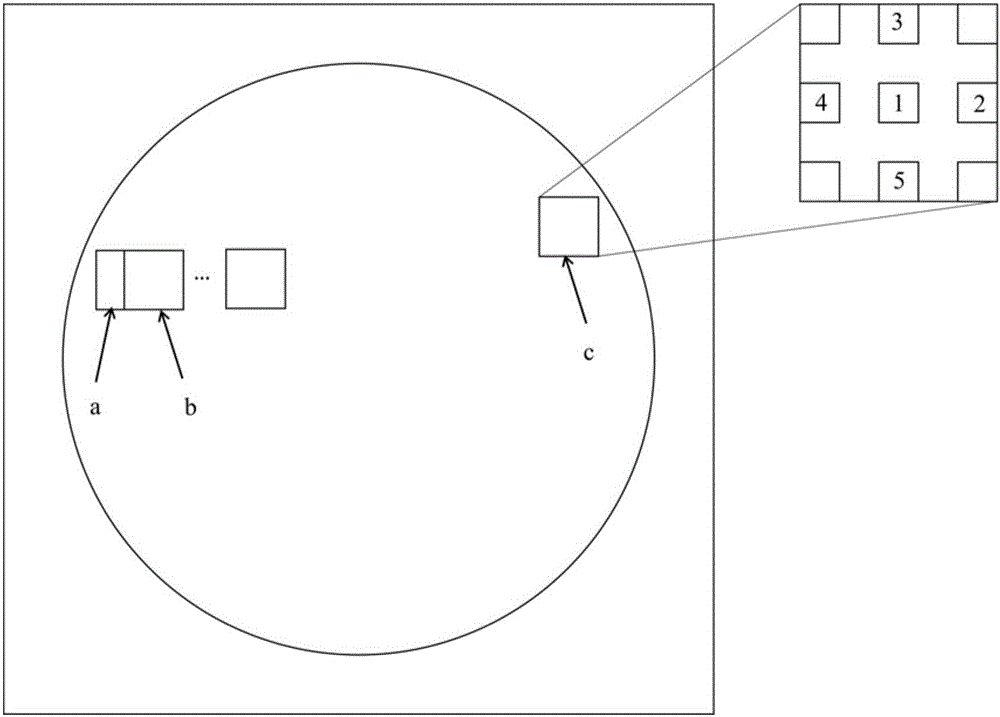
[0037] Step S120: Select the region of interest of the picture, select test pixels row by row in the region of interest with the first step length, and select a number of reference pixel points around the test pixel point with the second step length, each test pixel point and The surrounding reference pixels form a test unit, such as figure 2 The test units labeled a, b, and c, respectively. For example, in the test unit labeled c, 1 is the test pixel, and 2-5 are reference pixels. The number of reference pixels can be flexibly selected according to needs. The more reference pixels, the more accurate the test result.
[0038] Among them, the second step is longer than half of the first step, so that two adjacent test units in the sam...
Embodiment 2
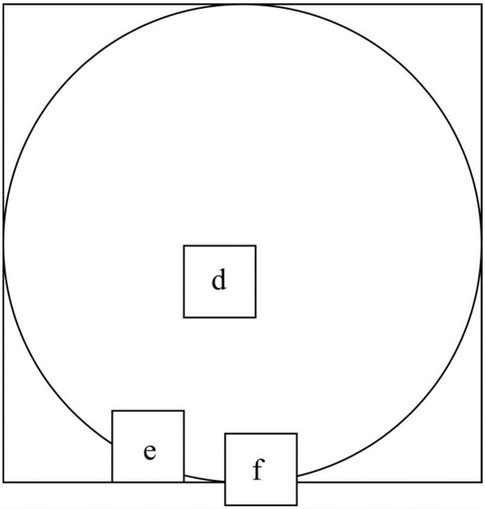
[0061] In the embodiment of the present invention, such as Figure 6 As shown, the image gradually darkens radially from the center to the edge. Since the brightness of the central area has a small change, while the brightness of the edge area has a large change, if the variance threshold is set to be uniform, it is easy to miss the slight stain with a small variance of the brightness value of the central area, and it is also easy to set the brightness of the edge area The place where the value variance itself is relatively large is misjudged as a stain. Therefore, when setting the variance threshold, the experience value corresponding to the area with a larger average brightness value is set smaller, and the experience value corresponding to the area with a smaller average brightness value is set larger, that is, the variance threshold of the central area is smaller than that of the edge The variance threshold for the region. For example, the variance corresponding to a cer...
Embodiment 3
[0065] Such as Figure 7 As shown, the embodiment of the present invention provides a device for detecting lens stains, the device comprising:
[0066] The variance threshold acquisition module 100 is used for:
[0067] Under the same shooting conditions as the test environment, take a picture with a non-stained lens or select a picture from a video shot with a non-stained lens;
[0068] Obtain the brightness values of the central pixel in the different brightness areas of the picture and several pixels in a predetermined step around it;
[0069] Calculate the average luminance value and the variance of the luminance value of several pixels within the central pixel point and its surrounding predetermined step;
[0070] The variance thresholds corresponding to different average brightness values are obtained by adding an empirical value to the variance of the average brightness value, and the empirical value varies with the average brightness value.
[0071] For a pictur...
PUM
 Abstract
Description
Claims
Application Information
 - R&D
- Intellectual Property
- Life Sciences
- Materials
- Tech Scout
- Unparalleled Data Quality
- Higher Quality Content
- 60% Fewer Hallucinations
Browse by: Latest US Patents, China's latest patents, Technical Efficacy Thesaurus, Application Domain, Technology Topic, Popular Technical Reports.
© 2025 PatSnap. All rights reserved.Legal|Privacy policy|Modern Slavery Act Transparency Statement|Sitemap|About US| Contact US: help@patsnap.com