A lens that directly produces a ring-shaped hollow focused beam

A focused beam and annular technology, applied in the field of optical lenses, can solve the problems of unfavorable practical application of annular hollow focused beams, difficulty in system installation and debugging, and difficulty in ensuring accuracy, so as to simplify the difficulty of system installation and debugging, low component cost, Easy to process effects

Active Publication Date: 2019-05-17
XIAMEN UNIV
View PDF3 Cites 0 Cited by
  • Summary
  • Abstract
  • Description
  • Claims
  • Application Information

AI Technical Summary

Problems solved by technology

However, these current methods still have their own shortcomings: in the geometric optics method, expensive axicon lenses are needed to shape the fundamental mode Gaussian beam; in the off-axis fiber method, multiple lenses are needed to couple the beam to In the optical fiber, the difficulty of debugging is increased, and the light conversion efficiency is low; in the phase photo method, the position of the phase photo relative to the lens needs to be precisely set to obtain an ideal annular hollow beam
On the other hand, the current method of generating a focused annular hollow beam is limited to using additional lenses to focus the already generated annular hollow beam [9-11,14], which makes the focusing system complex, difficult to operate, and difficult to guarantee accuracy
Based on this, these methods require more than one optical element, and are expensive, not only have the problem of high component cost, but also have the defect that the installation and debugging of the system are difficult, and the light conversion efficiency is also low, which is not conducive to the development of the annular hollow focused beam. practical application

Method used


Image

  • A lens that directly produces a ring-shaped hollow focused beam
  • A lens that directly produces a ring-shaped hollow focused beam
  • A lens that directly produces a ring-shaped hollow focused beam

Examples


Embodiment Construction

[0032] The following will clearly and completely describe the technical solutions in the embodiments of the present invention with reference to the drawings in the embodiments of the present invention. Apparently, the described embodiments are only some of the embodiments of the present invention, but not all of them.

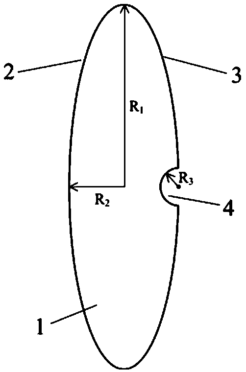
[0033] like figure 1As shown, the embodiment of the present invention is provided with convex lens 1, and convex lens 1 is provided with beam input surface 2 and beam output surface 3, is provided with concave cavity 4 at the center of the beam output surface 3 of convex lens 1, and the depth of concave cavity 4 is much smaller than The thickness of the central axis of the convex lens 1, the aperture of the concave cavity 4 is much smaller than the diameter of the convex lens 1, and the curvature of the surface of the concave cavity 4 is much larger than the curvature of the beam input surface 2 of the convex lens.

[0034] The section surface of the convex le...


PUM


Abstract

The invention relates to an optical lens and provides a lens capable of directly producing an annular hollow focus beam. The lens capable of directly producing an annular hollow focus beam comprises a convex lens having a beam input surface and a beam output surface. A concave cavity is provided at the center of the beam output surface of the convex lens. The depth of the concave cavity is much smaller than the thickness of the central axis part of the convex lens, the aperture of the concave cavity is much smaller than the diameter of the convex lens, and the curvature of the surface of the concave cavity is much larger than that of the beam input surface of the convex lens. An annular hollow focus beam can be obtained by focusing a parallelly-incident Gaussian beam and a focus spot can reach the micron level, so the very high power density and light conversion efficiency are achieved. In addition, the number of optical components is reduced, the practical application cost of the annular hollow focus beam is significantly reduced and the difficulty in system installation and debugging is effectively decreased, so the lens of the invention is applicable in various general occasions.

Description

technical field [0001] The invention relates to an optical lens, in particular to a lens that directly generates an annular hollow focused light beam. Background technique [0002] The laser beam has the characteristic of Gaussian distribution of energy, and the ring-shaped hollow laser beam can be obtained by spatially shaping the laser beam. The central light intensity of the annular hollow beam is zero, and it has spin angular momentum and orbital angular momentum. It is widely used in the fields of machining [1,2], biology [3], medicine [4] and military [5] middle. The focused ring-shaped hollow beam has a micron-scale focused spot and extremely high power density, which can effectively improve the performance of the ring-shaped hollow beam and further expand the application range of the ring-shaped hollow beam, for example, it can be used for optical particle manipulation [6-8] and as a Laser pump sources[9,10] and other fields. [0003] At present, there are many me...

Claims


Application Information

Patent Timeline
Patent Type & Authority Patents(China)
IPC IPC(8): G02B3/00G02B27/09
CPCG02B3/00G02B27/0927G02B27/0955G02B2003/0093
Inventor 董俊何宏森
Owner XIAMEN UNIV
Why Eureka
Try Eureka