
Concealed mechanical arm for vehicle machining

A built-in, robotic arm technology, applied in manipulators, manufacturing tools, etc., can solve the problems of large floor space, high equipment cost, complicated steps, etc., and achieve the effects of low cost, high processing efficiency, and convenient clamping and operation.

Inactive Publication Date: 2017-02-15
NANLING ZINGIBER MIOGA ROSE IND ASSOC
View PDF0 Cites 4 Cited by
  • Summary
  • Abstract
  • Description
  • Claims
  • Application Information

AI Technical Summary

Problems solved by technology

[0002] With the development of modern society, people's living standards are getting higher and higher. As a means of transportation, automobiles have entered most families. During the processing of auto parts, it is often necessary to weld, transfer, and The size of the equipment is completed by multiple manipulators, the steps are cumbersome and complicated, the equipment cost is high, and the floor area is large. Therefore, we propose a built-in manipulator for automobile processing to solve the above problems

Method used


Image

  • Concealed mechanical arm for vehicle machining
  • Concealed mechanical arm for vehicle machining

Examples


Embodiment Construction

[0014] The following will clearly and completely describe the technical solutions in the embodiments of the present invention with reference to the accompanying drawings in the embodiments of the present invention. Obviously, the described embodiments are only some of the embodiments of the present invention, not all of them.

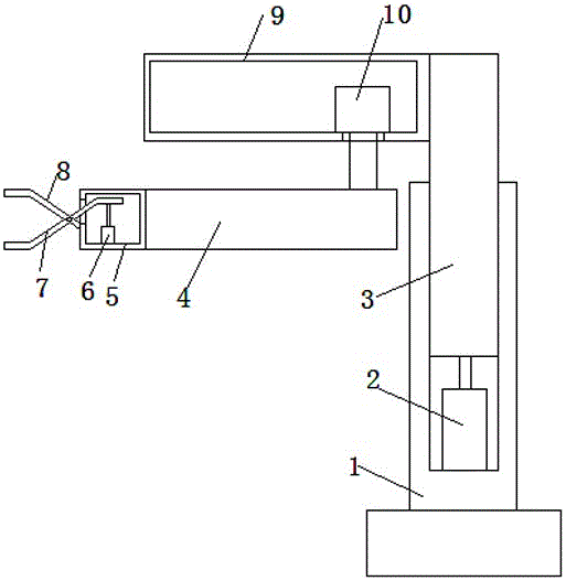
[0015] refer to Figure 1-2 , a built-in mechanical arm for automobile processing, including a base, a first support rod 1 is arranged on the base, a groove is provided on the top of the first support rod 1, a second support rod 3 is arranged in the groove, and a second support rod 3 is arranged in the groove A first cylinder 2 is provided on the inner wall of the bottom, the piston rod of the first cylinder 2 is connected with the second support rod 3, the side wall of the second support rod 3 is slidingly connected with the side wall of the groove, and the side wall of the second support rod 3 A housing 9 is installed on the top of the wall, and the i...


PUM


Abstract

The invention discloses a concealed mechanical arm for vehicle machining. The concealed mechanical arm for vehicle machining comprises a base; a first support rod is arranged on the base; a groove is formed in the top end of the first support rod; a second support rod is arranged in the groove; a first cylinder is arranged on the inner wall of the bottom of the groove; a piston rod of the first cylinder is connected with a second support rod; the side wall of the second support rod is slidingly connected with the side wall of the groove; a shell is mounted at the top end of the side wall of the second support rod; and a motor and a second cylinder are arranged in the shell. As the shell and a clamping box are arranged on the device, the second cylinder is arranged in the shell, and a piston rod of the second cylinder is connected with a welding head, when vehicle parts are clamped for transferring, the device can weld the vehicle parts; a welding device can extend on the shell without influencing transfer; and the first cylinder and the motor are arranged on the device to enable the device to move up and down and to rotate, so that the clamping operation is more convenient.

Description

technical field [0001] The invention relates to the technical field of automobile processing, in particular to a built-in mechanical arm for automobile processing. Background technique [0002] With the development of modern society, people's living standards are getting higher and higher. As a means of transportation, automobiles have entered most families. During the processing of auto parts, it is often necessary to weld, transfer, and The size of the equipment is completed by multiple manipulators, the steps are cumbersome and complicated, the equipment cost is high, and the floor space is large. Therefore, we propose a built-in manipulator for automobile processing to solve the above problems. Contents of the invention [0003] The purpose of the present invention is to solve the shortcomings in the prior art, and propose a built-in mechanical arm for automobile processing. [0004] In order to achieve the above object, the present invention adopts the following tech...

Claims


Application Information

Patent Timeline
IPC IPC(8): B25J11/00
CPCB25J11/005
Inventor 刘和勇
Owner NANLING ZINGIBER MIOGA ROSE IND ASSOC
Learn More