Combined voltage-withstanding detector

A pressure tester and a combined technology, applied in the electrical field, can solve problems such as long cycle time, low detection efficiency, and difficulty in meeting actual needs, and achieve the effect of improving detection efficiency and meeting market demand

Inactive Publication Date: 2017-02-08
JIANGMEN XIX TECH & ELECTRONICS CO LTD
View PDF4 Cites 0 Cited by
  • Summary
  • Abstract
  • Description
  • Claims
  • Application Information

AI Technical Summary

Problems solved by technology

In the existing market, the pressure tester mainly includes a jig, from installation to detection to disassembly, the whole cycle is long, the detection efficiency is low, and it is difficult to meet the actual needs

Method used


Image

  • Combined voltage-withstanding detector

Examples


Embodiment Construction

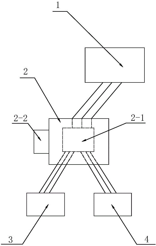
[0014] refer to figure 1 , a combined withstand voltage tester of the present invention includes a withstand voltage machine 1, a control box 2, and a first jig 3 and a second jig 4 for clamping a test piece, and the control box 2 can control the conversion The first jig 3 and the second jig 4 work to realize alternate operation and effectively improve detection efficiency.

[0015] refer to figure 1 , the control box 2 is provided with a connection part 2-1 and a control valve 2-2, one end of the connection part 2-1 is electrically connected to the pressure machine 1, and the other end is connected to the first jig 3 and the second jig 4 Electrical connection, that is, the first jig 3 and the second jig 4 are electrically connected to the pressure-resistant machine 1 through the connection part 2-1, and the control valve 2-2 is electrically connected to the connection part 2-1, and manually controlled The control valve 2-2 can realize the connection or disconnection of the ...


PUM


Abstract

The invention discloses a combined voltage-withstanding detector. The detector comprises a voltage withstanding device, a first tool for clamping a test piece, a second tool and a control box, the control box switches work between the first and second tools, and the control box is connected with the first tool, the second tool and the voltage withstanding device electrically. The combined voltage-withstanding detector is provided with the two tools and the control box, the control box can be used to switch working states of the two tools, when one tool is in the working state, the other tool can be mounted, alternative work is realized, the detecting efficiency is improved effectively, and the market requirements can be satisfied more.

Description

technical field [0001] The invention relates to the electrical field, in particular to a combined withstand voltage detector. Background technique [0002] At present, the electrical industry is developing rapidly, and more and more electrical products have emerged as the times require. Among them, transformers used to realize voltage conversion are becoming more and more important in more and more occasions. Voltage resistance, as an important performance of a transformer, has become an important indicator for judging the quality of a transformer. In the existing market, the withstand voltage tester mainly includes a jig. From installation to detection to disassembly, the whole cycle is long and the detection efficiency is low, which is difficult to meet the actual needs. Contents of the invention [0003] The present invention aims to solve one of the above-mentioned technical problems in the related art at least to a certain extent. For this reason, the present invent...

Claims


Application Information

Patent Timeline
Patent Type & Authority Applications(China)
IPC IPC(8): G01R31/12
CPCG01R31/12
Inventor 王以俭
Owner JIANGMEN XIX TECH & ELECTRONICS CO LTD
Why Eureka
Try Eureka