
Vehicle suspension and vehicle

A vehicle suspension and accumulator technology, which is applied to suspensions, elastic suspensions, vehicle components, etc., can solve the problem of incompatibility between vehicle ride comfort and handling stability, suspension stiffness and damping that cannot be adjusted or controlled, etc. problems, to achieve the effect of improving anti-rolling and anti-rollover performance, improving driving comfort, and improving comfort

Inactive Publication Date: 2019-04-09
张家口舒狮汽车科技有限公司
View PDF3 Cites 0 Cited by
  • Summary
  • Abstract
  • Description
  • Claims
  • Application Information

AI Technical Summary

Problems solved by technology

[0002] The vehicle suspension system is the core functional component of the vehicle, which is of great significance to the driving safety, comfort and handling stability of the vehicle. More and more people pay attention to it. The damping and stiffness of the traditional passive suspension cannot be adjusted after the design is completed, and the stiffness is relatively large, and the ride comfort and handling stability of the vehicle cannot be balanced
[0003] The current vehicle oil-pneumatic suspensions are mainly interconnected oil-pneumatic suspensions and semi-active damping control suspensions. The interconnected oil-pneumatic suspensions improve the anti-rolling performance by interconnecting the upper and lower oil cylinders of different wheel suspensions, and evenly distribute the wheel loads of multi-axis vehicles, but the suspension stiffness The suspension and damping cannot be adjusted; the semi-active damping control suspension can only perform damping control, and the suspension stiffness cannot be adjusted continuously. It has been effectively improved, and the vehicle body roll cannot be controlled during emergency steering, resulting in the handling stability not being able to be adaptively adjusted according to the working conditions

Method used


Image

  • Vehicle suspension and vehicle

Examples


Embodiment approach

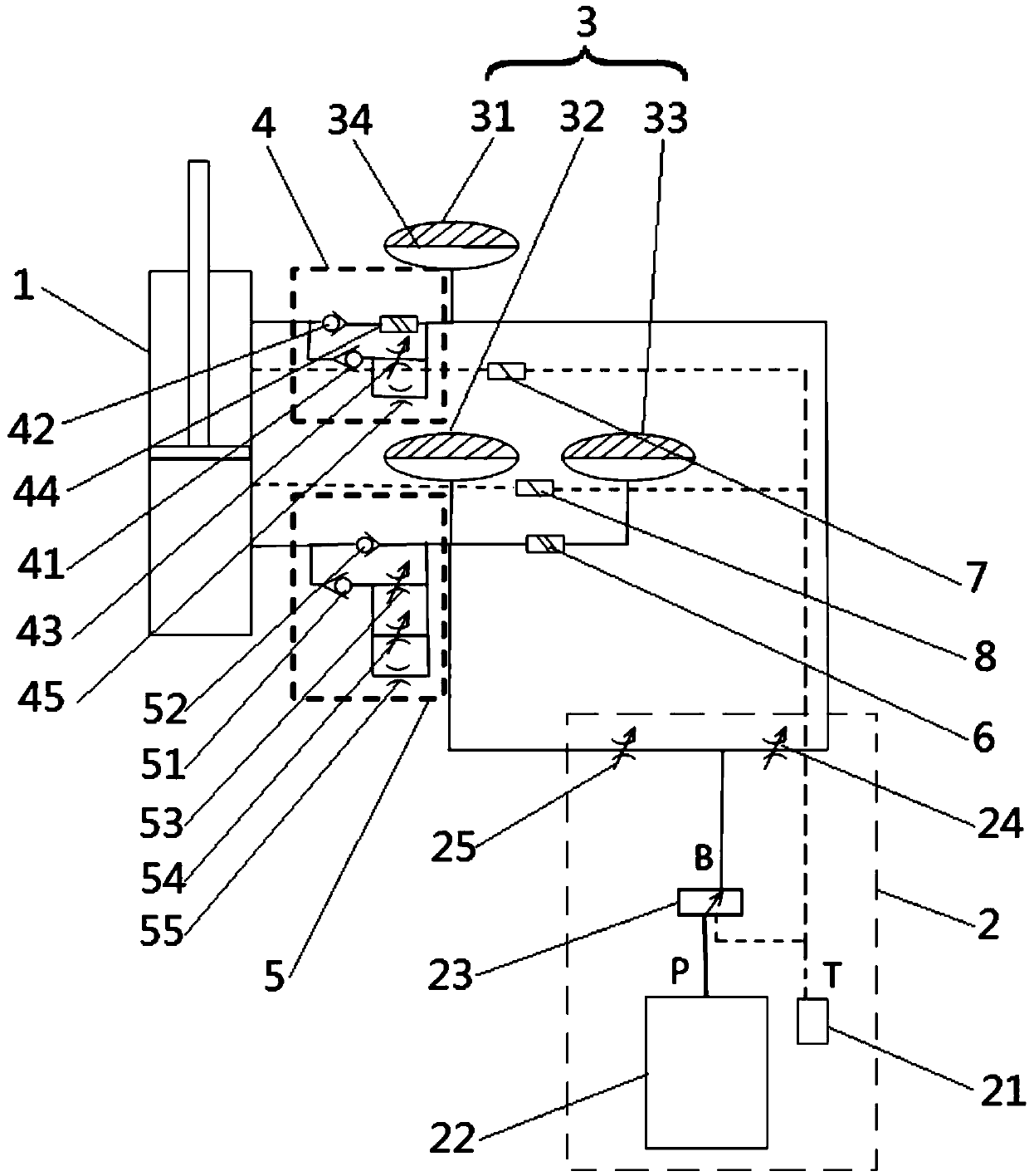
[0033] A preferred embodiment, the power unit 2 includes a fuel tank 21, a central accumulator 22, a reversing valve 23, a sixth solenoid valve 23 and a seventh solenoid valve 24, the fuel tank 21 communicates with the central accumulator 22, specifically In other words, the oil tank 21 communicates with the central accumulator 22 through the oil pump; the central accumulator 22 communicates with the reversing valve 23 through the oil pump, and the reversing valve 23 passes through the sixth solenoid valve 24, the third solenoid valve 44 and the second one-way valve in sequence. The valve 42 communicates with the rod chamber of the oil cylinder 1, and the reversing valve 23 communicates with the rodless chamber of the oil cylinder 1 through the seventh solenoid valve 25 and the fourth check valve 52, and alternately switches between the rod chamber and the non-rod chamber by controlling the reversing valve 23. The rod cavity is filled with oil to the desired pressure. Wherein,...


PUM


Abstract

The invention relates to a vehicle suspension and a vehicle. The suspension comprises an oil cylinder, a power unit and at least three accumulators, wherein a rod chamber of the oil cylinder is communicated with the first accumulator and the power unit respectively, and a rodless chamber of the oil cylinder is communicated with the second accumulator and the power unit respectively. The vehicle comprises the suspension which is arranged at the bottom of a vehicle body. The suspension and the vehicle have the beneficial effects that real-time and step adjustment of rigidity is achieved and the side-tipping and rollover resistance of the vehicle is improved, thus greatly improving the comfort, safety and handling stability of the vehicle; and the volume of the total air chamber of the accumulator connected with the rodless chamber of the oil cylinder is increased, thus reducing the rigidity of the suspension, so that the suspension is more flexible and then the vehicle runs more stably and comfortably.

Description

technical field [0001] The invention relates to the technical field of vehicle equipment, in particular to a vehicle suspension and a vehicle. Background technique [0002] The vehicle suspension system is the core functional component of the vehicle, which is of great significance to the driving safety, comfort and handling stability of the vehicle. More and more people pay attention to it. The damping and stiffness of the traditional passive suspension cannot be adjusted after the design is completed, and the stiffness is relatively large, and the ride comfort and handling stability of the vehicle cannot be balanced. [0003] The current vehicle oil-pneumatic suspensions are mainly interconnected oil-pneumatic suspensions and semi-active damping control suspensions. The interconnected oil-pneumatic suspensions improve the anti-rolling performance by interconnecting the upper and lower oil cylinders of different wheel suspensions, and evenly distribute the wheel loads of mu...

Claims


Application Information

Patent Timeline
Patent Type & Authority Patents(China)
IPC IPC(8): B60G21/073B60G17/04B60G17/08
CPCB60G17/0432B60G17/08B60G21/073
Inventor 卢文丽
Owner 张家口舒狮汽车科技有限公司
Learn More