
Circuit breaker

A circuit breaker and controller technology, applied in the direction of protection switch operation/release mechanism, etc., can solve the problems of low production efficiency, complex mechanism and high cost, and achieve the effects of low manufacturing cost, small size and good stability

Active Publication Date: 2017-02-01
JIANGYIN LIYUAN ELECTRONICS +1
View PDF5 Cites 6 Cited by
  • Summary
  • Abstract
  • Description
  • Claims
  • Application Information

AI Technical Summary

Problems solved by technology

[0002] With the popularization of the smart grid, small circuit breakers and residual current operated circuit breakers that require manual operation can no longer meet the requirements of the power grid. They must be matched with automatic reclosing, so that the circuit breaker will give a reclosing switch after a fault or misoperation. The signal can make the circuit breaker close automatically, without the need for maintenance workers to manually close the switch, realize remote control, and effectively save manpower and material resources. The motor drives the linkage mechanism to realize the automatic closing of the circuit breaker; 2. The matching of the steering gear and the spur gear drives the linkage mechanism to realize the automatic closing of the circuit breaker; 3. The matching of the steering gear and the bevel gear drives the linkage mechanism to realize the automatic closing of the circuit breaker. The above mechanisms are complicated , large volume, high cost and low production efficiency

Method used


Image

  • Circuit breaker
  • Circuit breaker

Examples


Embodiment Construction

[0019] The present invention will be further described below in conjunction with the accompanying drawings and specific embodiments.

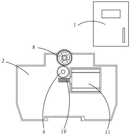
[0020] Such as Figure 1-Figure 2 As shown, the present invention discloses a circuit breaker, including a fee-controlled electric energy meter 1, a switch body, and a remote control module connected between the fee-controlled electric energy meter 1 and the switch body;

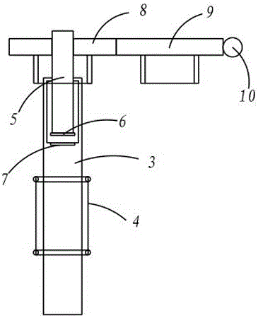
[0021] The switch body includes a switch base 2, an operating gate rotatably arranged on the switch base 2 for controlling closing or opening, the operating gate is connected to the switch base 2 through a rotating shaft 3 in rotation, A torsion spring 4 is arranged between the rotating shaft 3 and the switch base 2 so that the operating brake is in the opening position;

[0022] The upper part of the rotating shaft 3 has a perforation extending along its length direction, a clutch lever 5 is slidably arranged in the perforation, the bottom of the perforation is connected wi...


PUM


Abstract

The invention provides a circuit breaker which is simple in structure, low in manufacturing cost and high in stability. The circuit breaker comprises a cost-control electric energy meter, a switch body and a remote control module, wherein the switch body comprises a switch base, and an operating brake which is rotationally arranged on the switch base; the operating brake and the switch base are rotationally connected through a rotary shaft; a torsional spring is arranged between the rotary shaft and the switch base; a perforation hole is formed in the upper part of the rotary shaft; a clutching rod is glidingly arranged in the perforation hole; the bottom of the perforation hole is connected with a positioning groove; a positioning part matched with the positioning groove is arranged on the lower end part of the clutching rod; a screw thread section is arranged on the upper part of the clutching rod; a driving gear is rotationally arranged on the switch base; a threaded hole is formed in the center of the driving gear; a transmission gear is also rotationally arranged on the switch base; the transmission gear is meshed with a worm which is rotationally arranged on the switch base; the worm is driven by a motor to rotate; and the remote control module is connected with a controller of the motor and the cost-control electric energy meter.

Description

technical field [0001] The invention relates to a circuit breaker. Background technique [0002] With the popularization of the smart grid, small circuit breakers and residual current operated circuit breakers that require manual operation can no longer meet the requirements of the power grid. They must be matched with automatic reclosing lawns, so that the circuit breaker will give a recloser after a fault or misoperation. The signal can make the circuit breaker close automatically, without the need for maintenance workers to manually close the switch, realize remote control, and effectively save manpower and material resources. The motor drives the linkage mechanism to realize the automatic closing of the circuit breaker; 2. The matching of the steering gear and the spur gear drives the linkage mechanism to realize the automatic closing of the circuit breaker; 3. The matching of the steering gear and the bevel gear drives the linkage mechanism to realize the automatic clos...

Claims


Application Information

Patent Timeline
Patent Type & Authority Applications(China)
IPC IPC(8): H01H71/10H01H71/43H01H71/70
CPCH01H71/10H01H71/43H01H71/70
Inventor 陈文藻丁正林邓志敏周星华号李艳军
Owner JIANGYIN LIYUAN ELECTRONICS
Learn More