
Feeding mechanism of automatic low-level palletizer

A feeding mechanism and low-level code technology, which is applied in the stacking, transportation and packaging of objects, can solve the problems of less bricks, high labor intensity and low loading efficiency, and achieve shortened time and high stacking efficiency. , the effect of low labor intensity

Inactive Publication Date: 2018-12-04
NINGBO NOAH INTELLIGENT EQUIP
View PDF6 Cites 0 Cited by
  • Summary
  • Abstract
  • Description
  • Claims
  • Application Information

AI Technical Summary

Problems solved by technology

[0003] The existing brick processing equipment is generally equipped with pallets on which the bricks are shaped, and the formed bricks are sent to the maintenance site together with the pallets for maintenance. Before the vehicle, the bricks need to be palletized. In the traditional process, when the bricks are palletized, the bricks on each pallet are generally manually transported to the vehicle for palletizing. This palletizing mode causes the following Technical problems, 1. Workers need to repeatedly bend, stretch, take bricks, put bricks and other actions during the handling process, which makes the labor intensity of workers higher. In this case, the labor cost of workers is also higher; 2. 1. Manually loading each brick into a car, the speed is relatively slow, and the number of bricks transported at a time is less, resulting in a longer time for brick loading and lower loading efficiency

Method used


Image

  • Feeding mechanism of automatic low-level palletizer

Examples


Embodiment Construction

[0035] The following are specific embodiments of the present invention and in conjunction with the accompanying drawings, the technical solutions of the present invention are further described, but the present invention is not limited to these embodiments.

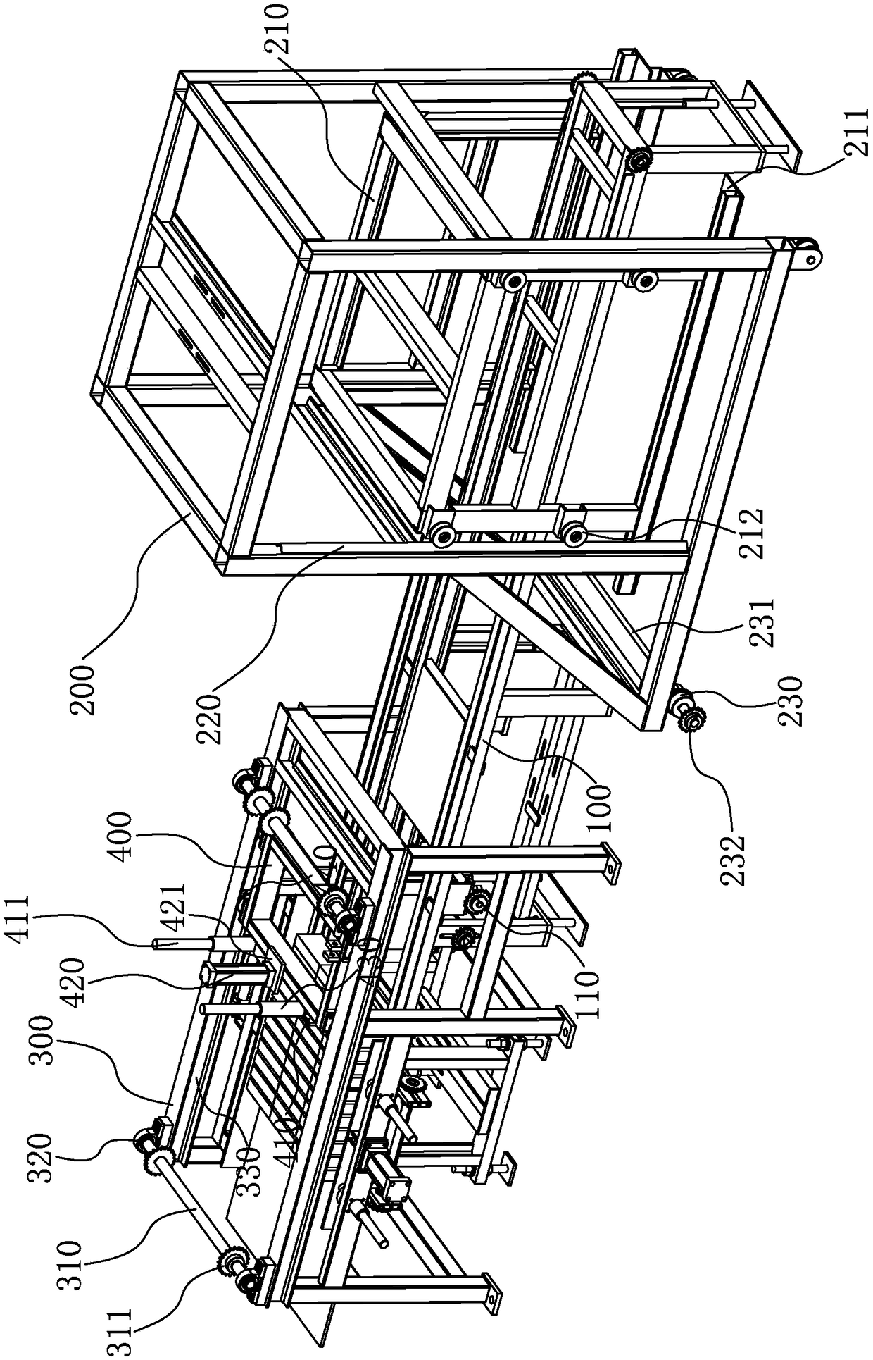
[0036] Such as figure 1 As shown, the feeding mechanism of the automatic low-level palletizer of the present invention includes a feeding frame 100, a feeding assembly, a discharging frame 300 and a pushing assembly.

[0037] The feeding frame 100 is a frame structure, which is arranged in the axial direction and has a feeding end and a discharging end.

[0038] The feeding assembly includes a moving frame 200 and a feeding frame 210. The moving frame 200 is a frame structure. The moving frame 200 can move axially relative to the feeding frame 100 and can move to the top of the feeding frame 100. The feeding frame 210 is also a frame structure. , which is arranged inside the moving frame 200 and can move vertically relati...


PUM


Abstract

The invention provides a feeding mechanism of an automatic lower stacker crane, and belongs to the technical field of automatic processing. The feeding mechanism of automatic lower stacker crane solves the technological problem that current brick stacker cranes have low effciency. The feeding mechanism of automatic lower stacker crane comprises a feeding frame, an inward feeding component, an outward feeding frame, and a feed pushing component. The feeding frame is arranged in an axial direction, and is provided with an inward feeding end and an outward feeding end; the inward feeding component is arranged on a feeding end and can move in an axial direction corresponding to an inward feeding frame; the outward feeding frame is arranged on the outward feeding end; the feed pushing component is arranged on the outward feeding frame and can move in an axial direction along the outward feeding frame. The feeding component can transport a layer board loaded with bricks to the feeding frame, and the layer board can move on the feeding frame, when the layer board moves to the outward feeding end, the feed pushing component pushes the bricks on the layer board and finally move the bricks off the feeding frame. The whole process is like the followings: the bricks are loaded on the layer board and transported to the feeding frame through the feeding component, and was pushed off the feeding frame through the feed pushing component, and finally the bricks enter the stacker crane where the bricks are stacked into a buttress. No labor needs to participate in the whole process, therefore the labor intensity of workers is lesser.

Description

technical field [0001] The invention belongs to the technical field of automatic processing, and relates to a feeding mechanism of an automatic low-position palletizer. Background technique [0002] The field of brick production has achieved mechanization and automation so far. Through automated mechanical equipment, continuous and uninterrupted processing of bricks has been realized, which has greatly improved production efficiency, replaced part of labor, and reduced labor intensity. [0003] The existing brick processing equipment is generally equipped with pallets on which the bricks are shaped, and the formed bricks are sent to the maintenance site together with the pallets for maintenance. Before the vehicle, the bricks need to be palletized. In the traditional process, when the bricks are palletized, the bricks on each pallet are generally manually transported to the vehicle for palletizing. This palletizing mode causes the following Technical problems, 1. Workers ne...

Claims


Application Information

Patent Timeline
Patent Type & Authority Patents(China)
IPC IPC(8): B65G57/20
CPCB65G57/20
Inventor 杨海波杨海斌
Owner NINGBO NOAH INTELLIGENT EQUIP
Learn More