Alarm monitoring method and system

A monitoring system and monitoring interface technology, applied in the field of power plants, can solve the problems that the operator cannot quickly identify the alarm components in the alarm area, the distribution of unfavorable alarms, and all the alarm items cannot be displayed on the screen, so as to save screen space and achieve alarm monitoring. good effect

Active Publication Date: 2017-01-18
中广核工程有限公司 +1
View PDF6 Cites 0 Cited by
  • Summary
  • Abstract
  • Description
  • Claims
  • Application Information

AI Technical Summary

Problems solved by technology

[0003] The present invention aims at the monitoring field of the power plant system, when the alarm list is used to monitor each area of ​​the power plant system, the alarm items displayed are dynamic, and the operator cannot quickly identify the alarm area and alarm components corresponding to the alarm items; at the same time , due to the limitation of screen space, all alarm items in the alarm list cannot be displayed on the screen, which is not conducive to the operator to understand the overall alarm distribution of the system. A method and system for alarm monitoring are proposed

Method used


Image

  • Alarm monitoring method and system
  • Alarm monitoring method and system
  • Alarm monitoring method and system

Examples


no. 1 example

[0048] The alarm monitoring method proposed in this embodiment includes the following steps:

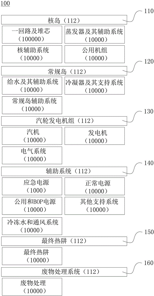
[0049] Step S1, divide the power plant system into several partitions and sub-partitions according to the functions of the power plant system; set an alarm monitoring interface 100, and the alarm monitoring interface 100 is fixedly provided with alarm monitoring sub-interfaces corresponding to the partitions and sub-partitions;

[0050] In this step, the alarm monitoring sub-interface includes a number of first sub-interfaces respectively corresponding to each partition of the power plant system, and also includes a number of Several second sub-interfaces; each second sub-interface corresponds to a first alarm indicator;

[0051] Such as figure 1 as shown, figure 1 The alarm monitoring interface 100 of this embodiment is shown, and the alarm monitoring interface 100 is divided into six first sub-interfaces according to each partition of the power plant system, and these first sub-i...

no. 2 example

[0082] The alarm monitoring method proposed in this embodiment includes the following steps:

[0083] Step S1, divide the power plant system into several partitions and sub-partitions according to the functions of the power plant system; set an alarm monitoring interface 100, and the alarm monitoring interface 100 is fixedly provided with alarm monitoring sub-interfaces corresponding to the partitions and sub-partitions;

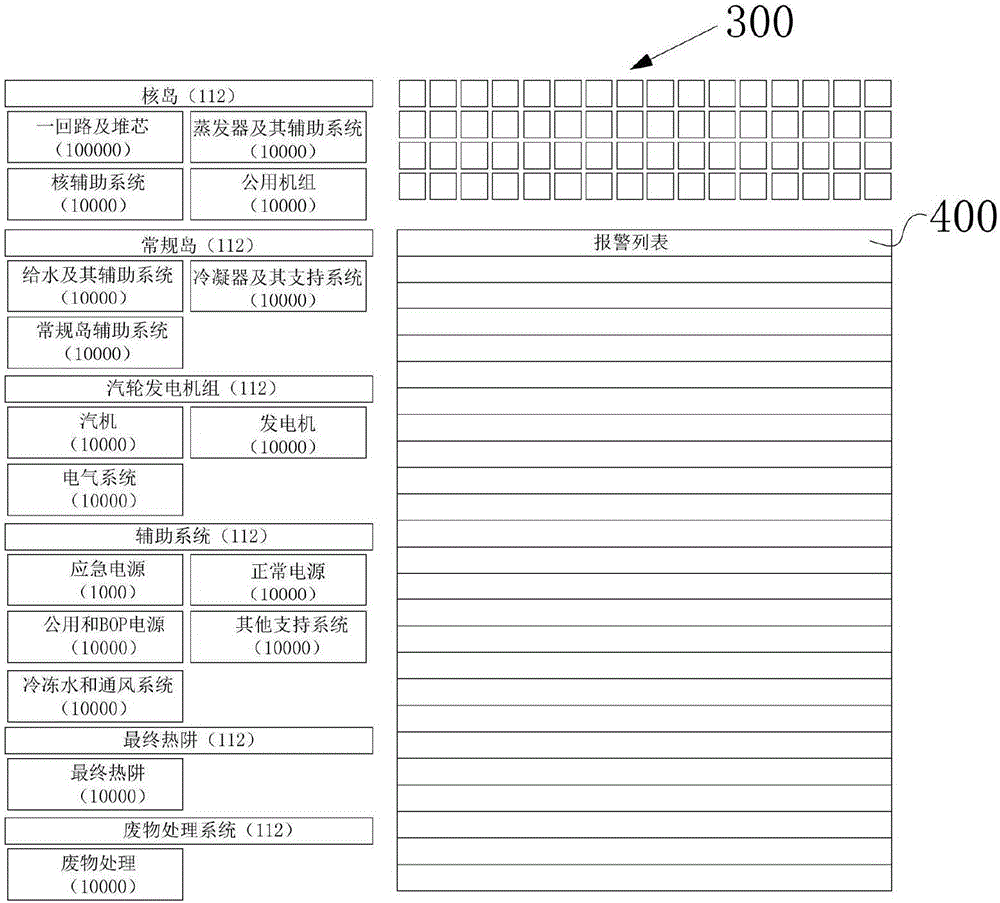
[0084] In this step, the alarm monitoring sub-interface includes a number of first sub-interfaces respectively corresponding to each partition of the power plant system, and also includes a number of Several second sub-interfaces; each second sub-interface corresponds to a first alarm indicator;

[0085] Such as Figure 4 as shown, Figure 4 The alarm monitoring interface 100 of this embodiment is shown, and the alarm monitoring interface 100 is divided into six first sub-interfaces according to each partition of the power plant system, and these first sub...


PUM


Abstract

The invention provides an alarm monitoring method and a system. The method comprises steps that step S1, a power plant system is divided into multiple partitions and sub partitions according to power plant system functions; an alarm monitoring interface (100) is set, and the alarm monitoring interface (100) is fixedly provided with alarm monitoring sub interfaces corresponding to the partitions and the sub partitions; step S2, alarm of the partitions and the sub partitions is monitored; according to alarm states and priority of the partitions or the sub partitions, an alarm signal according to the partitions or the sub partitions is outputted; step S3, in the corresponding alarm monitoring sub interfaces, an indication signal corresponding to the alarm signal is displayed; in the step S3, the indication signal is a signal displayed by the corresponding alarm monitoring sub interface with corresponding flicker frequency and color difference according to the alarm state and priority of each partition or the sub partition. The method is advantaged in that the method is visual and practical, and the alarm monitoring effect is good.

Description

technical field [0001] The invention relates to the field of power plants, in particular to an alarm monitoring method and system. Background technique [0002] With the application of digital instrument control system, in the monitoring field of power plant system, the traditional hardware optical plate alarm method is being replaced by the screen-based computerized alarm method. In a traditional control room, the alarm system uses a hardware light plate to display the alarm. On the computer screen, the alarm display mostly adopts the alarm list form. However, in the alarm list, the alarm items displayed are dynamic, and the operator cannot quickly identify the alarm areas and alarm components corresponding to the alarm items; at the same time, due to the limitation of the screen space, all alarm items in the alarm list cannot be fully displayed. It is displayed on the screen, which is not conducive to the operator's understanding of the overall alarm distribution of the ...

Claims


Application Information

Patent Timeline
IPC IPC(8): G05B19/048
CPCG05B19/048
Inventor 詹林钰徐晓梅刘至垚李广文剑波昌海吴一谦刘伟吴帝就吴官寅曾龙德谢永泉范文红王延阁
Owner 中广核工程有限公司
Why Eureka
Try Eureka