Automatic finite element calculation method and automatic finite element calculation system for flowing of fluid in pipeline

A finite element and internal fluid technology, applied in the field of finite element calculation methods and systems, can solve problems such as high requirements for operating skills, unfavorable comparative analysis and calculation, etc., to achieve the effects of improving analysis and solution efficiency, facilitating comparative research, and simple operation

Inactive Publication Date: 2017-01-11
张洪银
View PDF2 Cites 1 Cited by
  • Summary
  • Abstract
  • Description
  • Claims
  • Application Information

AI Technical Summary

Problems solved by technology

[0003] This conventional approach has certain defects: it requires high operational skills for problem researchers to use finite element calculation commercial software; for pipeline models of different sizes and shapes, it is necessary to repeatedly perform operations such as modeling, GUI operation, and result analysis Process, perform a series of repetitive operations; it is not conducive to comparative analysis and calculation of similar problems

Method used


Image

  • Automatic finite element calculation method and automatic finite element calculation system for flowing of fluid in pipeline
  • Automatic finite element calculation method and automatic finite element calculation system for flowing of fluid in pipeline

Examples


Embodiment Construction

[0033] The above-mentioned features and advantages of the present invention can be better understood after reading the detailed description of the embodiments of the present disclosure in conjunction with the following drawings. In the drawings, components are not necessarily drawn to scale, and components with similar related properties or characteristics may have the same or similar reference numerals.

[0034] Embodiment of the method for automatic finite element calculation of fluid flow in pipeline

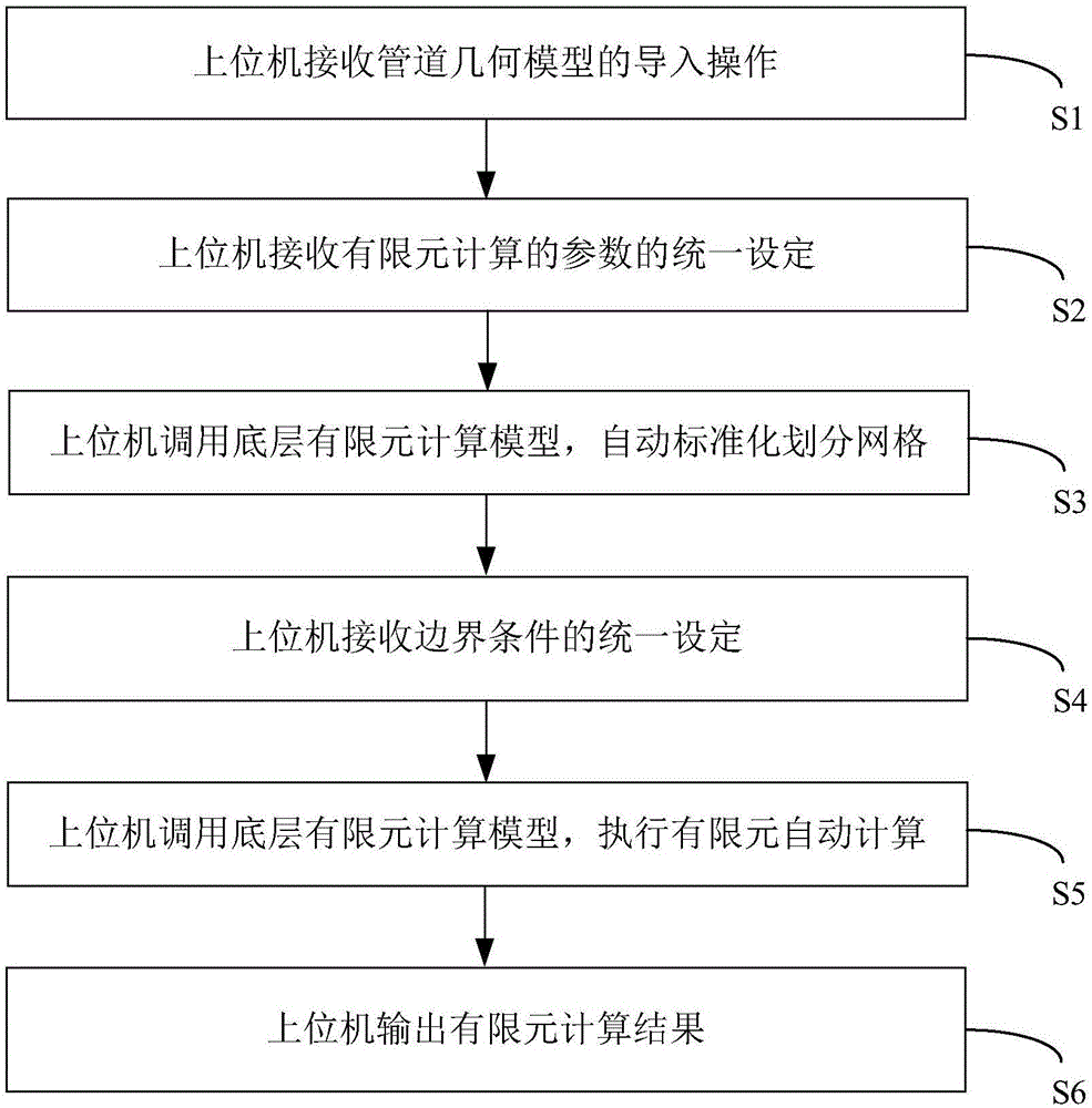
[0035] figure 1 The flow chart of a preferred embodiment of the method for automatic finite element calculation of fluid flow in a pipeline of the present invention is shown. See figure 1 , the implementation steps of the method of this embodiment are described in detail as follows.

[0036] Step S1: The upper computer receives the import operation of the pipeline geometric model.

[0037] The pipe in this embodiment can be a straight pipe or a bent pipe, and the cross ...


PUM


Abstract

The invention discloses an automatic finite element calculation method and an automatic finite element calculation system for flowing of fluid in a pipeline, which are capable of remarkably improving the research efficiency of related workers on the flowing problem of the fluid in the pipeline. The technical scheme provided by the invention is that the automatic finite element calculation method comprises the following steps: an upper computer receives an importing operation of a geometric model of the pipeline; the upper computer receives unified setting of parameters for finite element calculation; the upper computer calls a bottom layer finite element calculation model, and automatically divides grids in a standardized manner; the upper computer receives unified setting of boundary conditions; the upper computer calls the bottom layer finite element calculation model, and executes automatic finite element calculation; the upper computer outputs a finite element calculation result.

Description

technical field [0001] The invention relates to a finite element calculation method and system, in particular to an automatic finite element calculation method and system for fluid flow in pipelines. Background technique [0002] The problem of fluid flow in pipelines is a relatively common fluid problem, such as the flow of water in water pipes, the flow of oil in oil pipelines, and the flow of blood in blood vessels. At present, the common way to do research on related issues is to use mature finite element fluid calculation commercial software (such as Ansys, Fluent, etc.) to perform finite element calculations through the GUI interface of the software itself, and analyze and solve problems according to the calculation results. [0003] This conventional approach has certain defects: it requires high operational skills for problem researchers to use finite element calculation commercial software; for pipeline models of different sizes and shapes, it is necessary to repeat...

Claims


Application Information

Patent Timeline
Patent Type & Authority Applications(China)
IPC IPC(8): G06F17/50
CPCG06F30/23
Inventor 张洪银祁小龙罗媛媛
Owner 张洪银
Why Eureka
Try Eureka