Buoyancy adjusting device for snake-shaped amphibious robot and amphibious robot
A buoyancy adjustment and robot technology, applied in the field of robots, can solve the problems that robots cannot carry a large amount of energy to float and sink, and achieve the effects of convenient implementation, small footprint and energy saving.
- Summary
- Abstract
- Description
- Claims
- Application Information
AI Technical Summary
Problems solved by technology
Method used
Image
Examples
Embodiment 1
[0050] Embodiment 1: refer to Figure 1-10 .
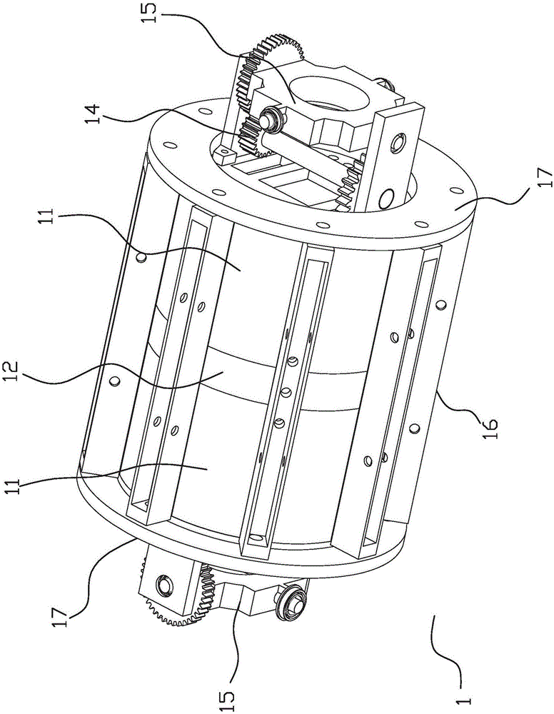
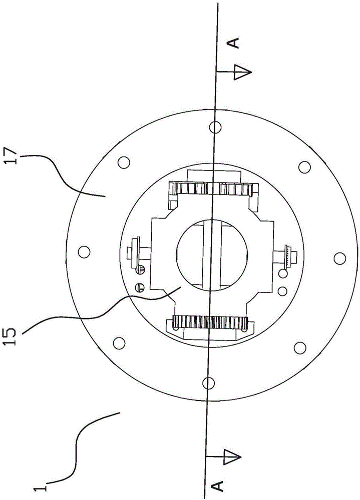
[0051] Specific reference Figure 1-5 , a snake-shaped amphibious robot with modular joints, comprising a plurality of general-purpose modules 1 connected end to end in series, the first general-purpose module 1 and the last general-purpose module 1 of the snake-shaped amphibious robot are respectively A head protection shell 3 and a tail protection shell 4 are provided. In this embodiment, the head protection shell 3 is cylindrical, and the tail protection shell 4 is conical-like. In the actual implementation of the present invention, the implementer can According to the implementation conditions, the shape of the appropriate head protection shell 3 and the tail protection shell 4 is selected. A retractable waterproof corrugated sheath 2 is arranged between the two adjacent general modules 1, and the two ends of the waterproof corrugated sheath 2 are connected. At the corresponding ends of the two adjacent universal modules 1, ...
Embodiment 2
[0080] Embodiment 2: refer to Figure 11-13 .
[0081] This embodiment is basically the same as Embodiment 1, the difference is:
[0082] In this embodiment, the telescopic driving mechanism is a driving motor 57 , and the telescopic connecting rod is a positive and negative threaded connecting rod 58 driven by the driving motor 57 .
[0083] Preferably, the central positions of the two connecting seats 52 are provided with threaded holes for matching the positive and negative threaded connecting rods 58 , and the intersection of the positive and negative threads of the positive and negative threaded connecting rods 58 is located at the center of the two connecting seats 52 at the midpoint of the line.
[0084] In this embodiment, the driving motor is a threaded motor. When the driving motor 57 rotates in the forward direction, it drives the forward and reverse threaded connecting rod 58 connected to it to rotate, and the rotation direction is the same as that of the driving...
PUM
 Abstract
Description
Claims
Application Information
 - R&D
- Intellectual Property
- Life Sciences
- Materials
- Tech Scout
- Unparalleled Data Quality
- Higher Quality Content
- 60% Fewer Hallucinations
Browse by: Latest US Patents, China's latest patents, Technical Efficacy Thesaurus, Application Domain, Technology Topic, Popular Technical Reports.
© 2025 PatSnap. All rights reserved.Legal|Privacy policy|Modern Slavery Act Transparency Statement|Sitemap|About US| Contact US: help@patsnap.com


