
Knob structure

A knob and knob cap technology, which is applied to control components, instruments, mechanical control devices, etc., can solve the problems of easy slipping, affecting the use of knobs, and detachment of knob caps from connecting shafts, etc., to prolong service life, facilitate maintenance, cost reduction effect

Active Publication Date: 2017-01-04
HYTERA COMM CORP
View PDF6 Cites 2 Cited by
  • Summary
  • Abstract
  • Description
  • Claims
  • Application Information

AI Technical Summary

Problems solved by technology

After using for a period of time, it is easy to slip between the knob cap and the connecting shaft, so that the knob cap and the connecting shaft are separated, affecting the use of the knob

Method used


Image

  • Knob structure
  • Knob structure
  • Knob structure

Examples


Embodiment Construction

[0032] In order to make the above objects, features and advantages of the present invention more comprehensible, specific implementations of the present invention will be described in detail below in conjunction with the accompanying drawings. In the following description, numerous specific details are set forth in order to provide a thorough understanding of the present invention. However, the present invention can be implemented in many other ways different from those described here, and those skilled in the art can make similar improvements without departing from the connotation of the present invention, so the present invention is not limited by the specific implementations disclosed below.

[0033] It should be noted that when an element is referred to as being “fixed” to another element, it can be directly on the other element or there can also be an intervening element. When an element is referred to as being "connected to" another element, it can be directly connected ...


PUM


Abstract

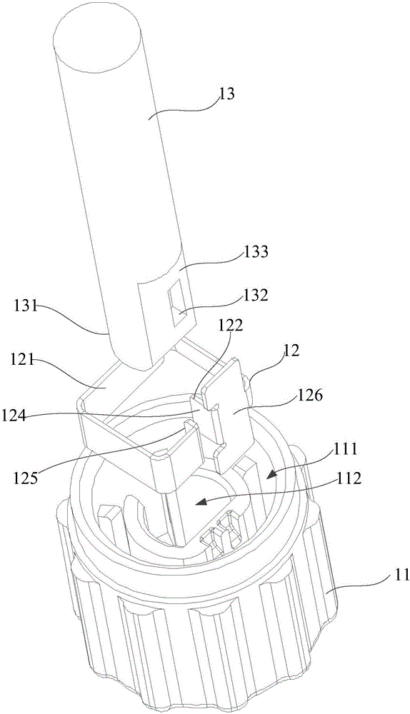
The invention provides a knob structure. The knob structure comprises a knob cap, a hoop and a rotating shaft, wherein an accommodating slot is formed in the knob cap; a limiting slot is formed in the bottom of the accommodating slot; a notch is formed in the side wall of the limiting slot; the outer side of the limiting slot is sleeved with the hoop; the hoop comprises an annular body and an elastic arm; the elastic arm is arranged towards the interior of the body; the elastic arm is accommodated in the notch, and is arranged as a magnetizer; one end of the rotating shaft is accommodated in the limiting slot; a clamping slot is formed in the side wall of the rotating shaft; a free end of at least one elastic arm penetrates through the notch and enters the clamping slot; the elastic arm elastically deforms under the effect of a magnetic field so as to enter and exit from the clamping slot, so that the hoop and the rotating shaft can be detachably connected with each other; the rotating shaft is connected with the knob cap through the elastic arm; the rotating shaft is tightly clamped by the elastic arm and cannot move outwards, so that the knob cap is stably connected with the rotating shaft. The knob structure can effectively promote the plugging and inserting effect of the rotating shaft. The service life of the knob structure is prolonged.

Description

technical field [0001] The invention relates to accessories of electronic equipment, in particular to a knob structure. Background technique [0002] The knob is a manual control element connected with the switch to control the opening or opening degree of the switch. Its edge is generally engraved with one or a series of labels, most of which are circular convex structures, discs, etc., so that it can realize Rotary control of the knob. At present, most traditional knobs include a knob base, a knob cap, and a connecting shaft, and the knob cover is connected to the knob base through the connecting shaft. Usually, the connecting shaft is provided with an external thread, and the knob cap and the connecting shaft are threaded. After being used for a period of time, slipping is likely to occur between the knob cap and the connecting shaft, so that the knob cap is separated from the connecting shaft, which affects the use of the knob. Contents of the invention [0003] The...

Claims


Application Information

Patent Timeline
IPC IPC(8): G05G1/10
CPCG05G1/10
Inventor 王全搌吴玉中李逸勇耿少伟于步野骆树青
Owner HYTERA COMM CORP
Learn More