
L-shaped combined type piston ring for internal combustion engine

A piston ring and combined technology, applied in the direction of piston rings, mechanical equipment, engine components, etc., can solve problems such as unfavorable combustion, harmful space, and increased emission pollution of internal combustion engines, and achieve the goal of eliminating harmful space, improving emissions, and reducing mechanical losses Effect

Inactive Publication Date: 2017-01-04
陆懋增
View PDF7 Cites 2 Cited by
  • Summary
  • Abstract
  • Description
  • Claims
  • Application Information

AI Technical Summary

Problems solved by technology

[0003] In order to prevent the head of the piston ring from pulling the cylinder, the traditional first piston ring has a distance of 0.12-0.22D (cylinder diameter) mm from the top of the piston. Within this distance, there is a gap of 0.25-0.4 mm between the piston and the cylinder wall, which is harmful. Space, which is not good for combustion, increases the emission pollution of internal combustion engines

Method used


Image

  • L-shaped combined type piston ring for internal combustion engine
  • L-shaped combined type piston ring for internal combustion engine
  • L-shaped combined type piston ring for internal combustion engine

Examples


Embodiment Construction

[0017] specific implementation plan

[0018] The present invention will be further described below in conjunction with accompanying drawing:

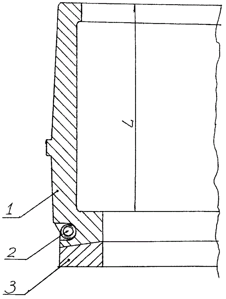
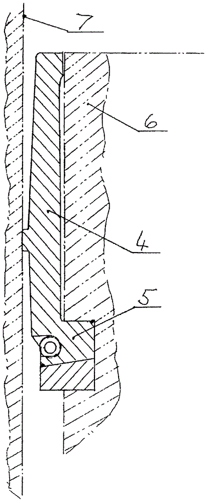
[0019] Such as figure 1 , 2 As shown, the L-shaped combined piston ring for an internal combustion engine is composed of a main ring 1, a coil spring 2 and a ring gasket 3. 90°, the short arm 5 and the ring pad 3 are coupled and installed in the piston ring groove, and the top of the long arm 4 is flush with the top of the piston 6 at this moment. The main ring 1 is a split structure, which can be divided into 4, 6, and 8 equal parts in the circumferential direction, and is locked into a ring by the coil spring 2 located in the outer circular groove of the short arm 5 . There is a gap between the inner side of the long arm 4 and the piston 6, and it communicates with the cylinder. The pressure in the cylinder can act on the inner side of the long arm 4. When the inner side of the long arm 4 is stressed, each equal portion will be di...


PUM


Abstract

The invention discloses an L-shaped combined type piston ring for an internal combustion engine. The L-shaped combined type piston ring is mainly composed of a main ring, a spiral spring and a ring cushion. The section of the main ring is in an L shape, the main ring is provided with a long arm and a short arm, and the long arm and the short arm form a 90-degree included angle. The short arm and the ring cushion are coupled and mounted into a piston ring groove, and the top of the long arm is flush with the top of a piston at the moment. The main ring is in a split type and can be equally divided into four or six or eight parts circumferentially, and the parts are locked into a circular ring through the spiral spring on the outer side of the short arm. When cylinder pressure acts on the inner side face of the long arm, the long arm is deflected and pressed to the cylinder wall, a protrusion ring on the outer side of the long arm and the cylinder wall form a first sealing edge, the upper side of the short arm and the upper edge of the piston ring groove form a second sealing edge at the moment, and the lower bottom face of the ring cushion and the lower edge of the piston ring groove form a third sealing edge. The sealing pressure of the piston ring can be changed from a traditional large constant value to a change value changing along with the air cylinder pressure, the mean valve of the change value is greatly smaller than the constant value, the mechanical loss of the internal combustion engine is reduced by one third to half, and the net power can be increased by 10-20%; and meanwhile, emission is improved. The L-shaped combined type piston ring can be widely applied to various internal combustion engines.

Description

technical field [0001] The invention relates to a piston ring for an internal combustion engine, in particular to a combined piston ring with an L-shaped section for an internal combustion engine. Background technique [0002] Piston rings are the key parts for sealing and oil distribution between the piston and cylinder liner in internal combustion engines. Since the development of internal combustion engines for nearly 200 years, integral piston rings with annular openings and rectangular cross-sections have always been used ( Figure 4 ), when sealing, use the radial pressure (sealing pressure) generated by heat treatment and assembly deformation during the manufacturing process to seal. It is a constant constant in the working process of the cylinder, that is, the normal pressure seal. In order to work reliably, this radial pressure must be determined according to the most stringent conditions in the four cycles of intake, compression, combustion expansion and exhaust in ...

Claims


Application Information

Patent Timeline
Patent Type & Authority Applications(China)
IPC IPC(8): F02F5/00
Inventor 陆懋增
Owner 陆懋增
Learn More