
Control Unit Structure of Motorcycle Anti-skid Braking System

A system control unit, anti-skid brake technology, applied in the direction of bicycle brakes, brakes, bicycle accessories, etc., can solve the problems of poor brake feel, too long oil pipe, long oil pipe 14, etc., to improve the brake feel and use Efficacy, the effect of shortening the length

Active Publication Date: 2019-03-05
KYMCO
View PDF8 Cites 0 Cited by
  • Summary
  • Abstract
  • Description
  • Claims
  • Application Information

AI Technical Summary

Problems solved by technology

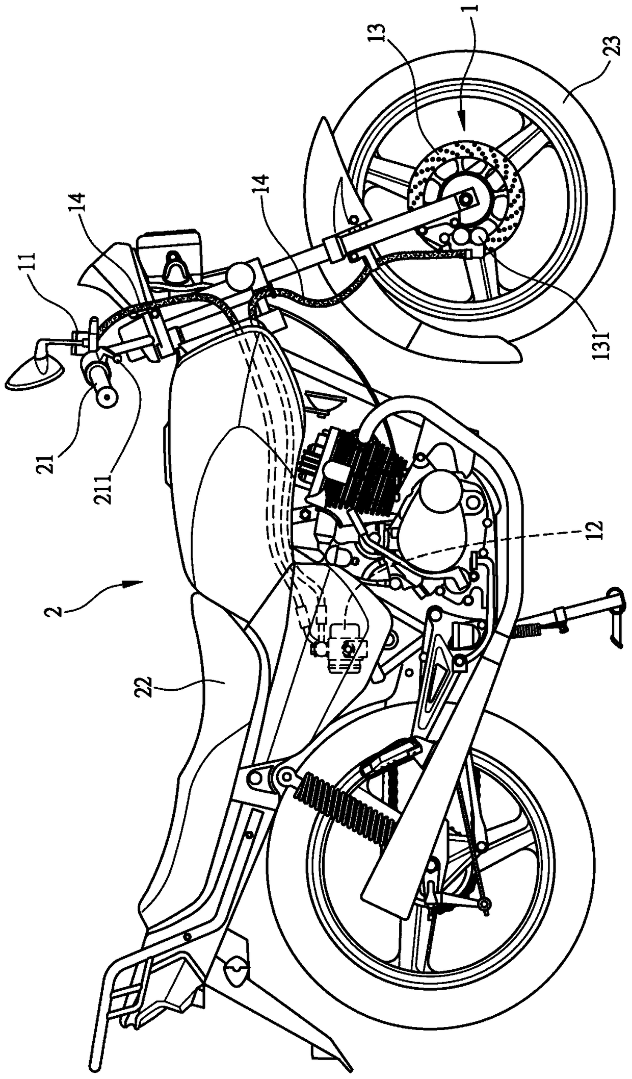
[0005] see again figure 1 As shown, the control unit 12 of the anti-skid braking system 1 is installed under the seat cushion 22 near the center of the motorcycle 2, so the overall length of the oil pipe 14 of the anti-skid braking system 1 becomes very long
When the overall length of the oil pipe 14 of the anti-skid brake system 1 becomes longer, in addition to complicating the piping engineering of the oil pipe 14, it will also cause the oil pressure in the oil pipe 14 to expand too much due to the length of the oil pipe 14 being too long, thereby making the driving People's brake feel becomes worse; at the same time, when the overall length of the oil pipe 14 of the anti-skid brake system 1 becomes longer, the cost of the anti-skid brake system 1 will undoubtedly be greatly increased.
[0006] Therefore, how to provide a structure of the control unit of the motorcycle anti-skid brake system to effectively solve the defect that the oil pipe is too long due to the setting of the control unit of the conventional motorcycle anti-skid brake system

Method used


Image

  • Control Unit Structure of Motorcycle Anti-skid Braking System
  • Control Unit Structure of Motorcycle Anti-skid Braking System
  • Control Unit Structure of Motorcycle Anti-skid Braking System

Examples


Embodiment Construction

[0016] In order to make it easier for your examiners to understand the structure of the present invention and the effects it can achieve, the accompanying drawings are hereby described as follows;

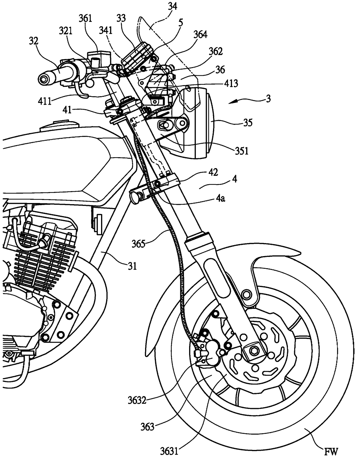
[0017] First, see figure 2 As shown, the front fork group 4 is connected to the front of the frame unit 31 of the motorcycle 3 (especially a straddle type motorcycle), and the front fork group 4 has an upper connecting plate 41 and a lower connecting plate 42. The steering handle 32 is arranged on the plate 41 , and the front wheel FW is pivotally arranged at the lower end of the front fork set 4 .

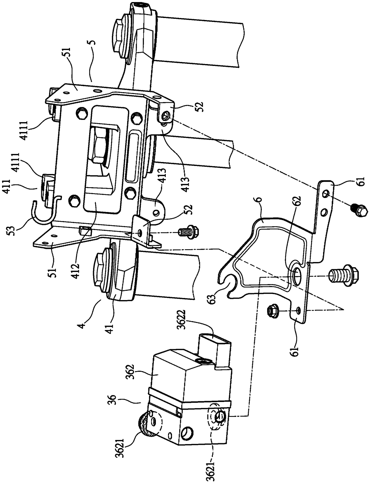
[0018] Such as figure 2 , 3 As shown, the upper connecting plate 41 is provided with a connecting portion 411 protruding toward the top of the motorcycle 3, and a steering handle connecting platform 4111 is arranged above the connecting portion 411, and the steering handle 32 is arranged on the steering handle connecting platform 4111. The upper connecting plate 41 is provided wit...


PUM


Abstract

The invention relates to a motorcycle anti-skid braking system control unit structure. A frame unit of a motorcycle is connected with a front fork group and is provided with an upper connected plate and a lower connected plate, as well as a steering handle and a console, and a front wheel is pivotally arranged on the lower end of the front fork group; an anti-skid braking system consists of a braking oil pump, a control unit and a butterfly braking unit, a braking oil pump oil pipe is connected between the braking oil pump and the control unit, a butterfly braking clamp oil pipe is connected between the control unit and a butterfly braking clamp of the butterfly braking unit, and the control unit is arranged in front of the upper connected plate and below the console. The control unit is arranged in front of the upper connected plate and below the console, therefore, the braking oil pump oil pipe and the butterfly braking clamp oil pipe can be arranged in the front of the motorcycle in a compact manner, so that the lengths of the braking oil pump oil pipe and the butterfly braking clamp oil pump can be effectively shortened; and the control unit can do synchronous rotation together with the steering handle, so that the braking oil pump oil pipe can be prevented from being pulled, and the use effect of the anti-skid braking system can be further promoted.

Description

technical field [0001] The invention relates to a control unit structure of a motorcycle anti-skid brake system, in particular to a control unit structure of a motorcycle anti-skid brake system which can prevent the oil pipe of the anti-skid brake system from being too long and further improve the efficacy of the anti-skid brake system. Background technique [0002] In the market of motorcycle manufacturing, sales and use, new models with high performance and high speed are important factors to maintain the life cycle of the motorcycle in the market. In response to this trend, high-performance braking systems are constantly being researched Improvement, however, motorcycles move by the friction between the front and rear wheels and the ground. If you only increase the braking force, you cannot stop the car safely and quickly, but may cause the motorcycle to slip . Therefore, anti-skid brake system ABS (Anti-Lock Brake System, anti-skid brake system) has been installed on mo...

Claims


Application Information

Patent Timeline
Patent Type & Authority Patents(China)
IPC IPC(8): B60T8/176B62L3/02
CPCB60T8/176B62L3/023
Inventor 何荣华蓝少斌
Owner KYMCO
Learn More