Multi-function marking machine

An engraving machine, multi-functional technology, applied in the directions of printing, stamping, single object, etc., can solve the problems of not being able to print and label the surface of small circular workpieces, and unable to automatically automatically cylindrical workpieces, etc., to achieve compact structure, Low manufacturing cost and small size

Active Publication Date: 2018-06-01
菏泽市特别特模板有限公司
View PDF10 Cites 0 Cited by
  • Summary
  • Abstract
  • Description
  • Claims
  • Application Information

AI Technical Summary

Problems solved by technology

This technology cannot be used for surface graphic printing of small round workpieces, nor can it automatically package and label cylindrical workpieces at the same time

Method used


Image

  • Multi-function marking machine
  • Multi-function marking machine
  • Multi-function marking machine

Examples


Embodiment Construction

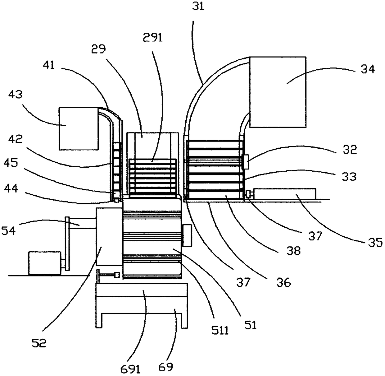
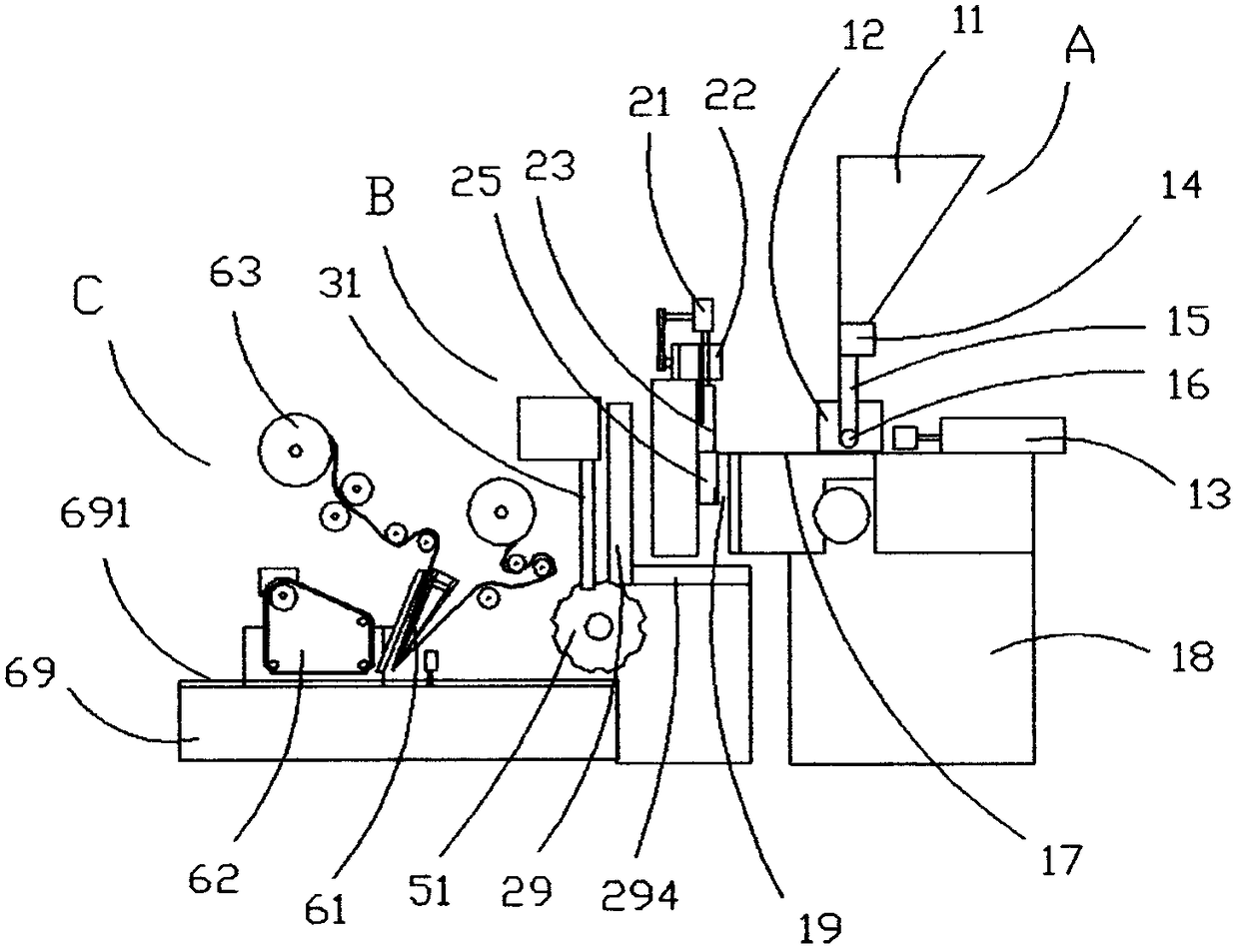
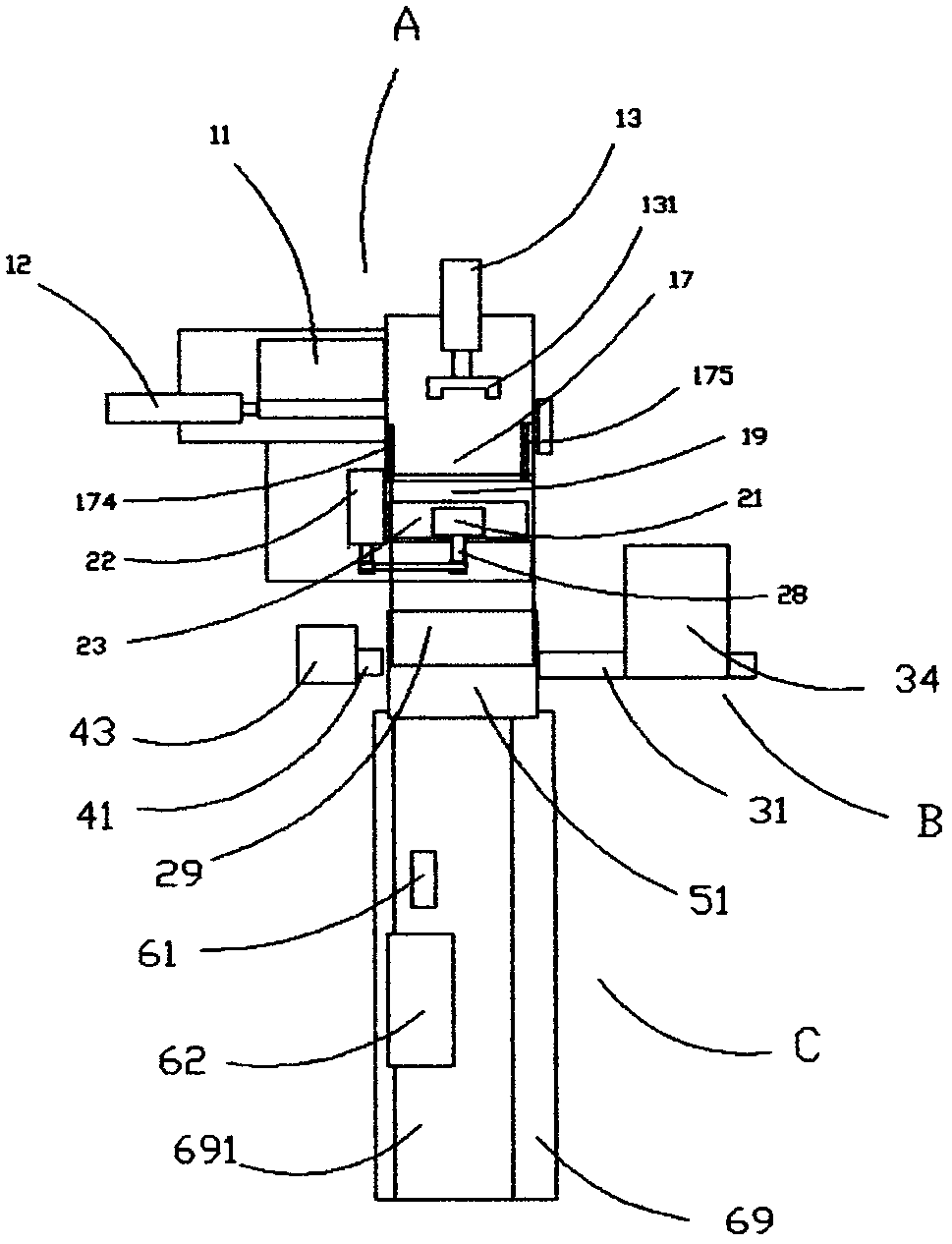
[0028] Such as figure 1 , 2 , 3, a multi-functional marking machine, including a printing system A, a packaging system B, a labeling device C, a feeding table 17 is provided above the support seat 18 of the printing system, and two forming parts are arranged on the feeding table 17. The power mechanism I13 and the power mechanism II12 installed at right angles, the bottom of the hopper 11 is provided with a distributor 14, the discharge holes 16 on both sides of the lower material channel 15 are on the same axis as the push rod of the power mechanism II12, and the power mechanism I13 The top of the push rod is provided with a Π-shaped push piece 131, and the two top surfaces of the push piece 131 are parallel to the sliding pressure surface on the outside of the feeding table 17. Both sides of the feeding table 17 are provided with an adjustment block 174 and a spring baffle 175. The slider 23 is fixed in the guide rail of the seat plate by the pressure plate 26 and the bolt ...


PUM


Abstract

A multifunctional imprinting machine is composed of a printing system, a packaging system and a labeling device. A support base feeding table of the printing system is provided with a power mechanism I and a power mechanism II. A material distributor is arranged below a hopper. A connecting rod of an eccentric wheel is connected with a sliding block and a die head provided with a character die. A downward sliding groove for rolling imprinting is formed between the die head and the feeding table. The packaging system comprises a cylinder conveying frame, a cover conveying frame, a workpiece output frame and a rotating wheel. The rotating wheel rotates in a gap to package a workpiece. A brand unsealing cutter is suspended above a conveying belt of the labeling device, and the front face of the unsealing cutter is provided with a baffle and a leveling device. A feeding disc contains rolled brand belts, after being divided through a cutting hobbing cutter, the label belts extend and are attached and connected to the unsealing cutter, and a label layer unsealed through the unsealing cutter moves in a packaging cylinder to automatically paste the packaging cylinder.

Description

technical field [0001] The invention relates to a device for printing on the surface of a workpiece, in particular to a multifunctional marking machine for printing, packaging and labeling a cylindrical workpiece. Background technique [0002] The specifications, trademarks, codes and other markings on the surface of the drill bit are currently stamped by hand. This method is labor-intensive, low in efficiency, and the fonts are of different depths, which affects the visual aesthetics and quality of the product. Someone once invented a fast cylindrical workpiece coding machine (notification number CN101774310), which includes a base, a main shaft, a type box and a type, a motor and a gearbox, a built-in motor and a gearbox in the base, and a type box clamp Tight font, install a circular feeding tray obliquely on the machine base, a baffle is installed on the rear side of the circular feeding tray, a bracket is fixedly obliquely installed on the machine base, the main shaft s...

Claims


Application Information

Patent Timeline
Patent Type & Authority Patents(China)
IPC IPC(8): B41K3/20B41K3/62B65B5/04B65B61/26
CPCB41K3/20B41K3/62B65B5/04B65B61/26
Inventor 杨志平
Owner 菏泽市特别特模板有限公司
Why Eureka
Try Eureka