Small Cylindrical Workpiece Marking Machine

A cylindrical workpiece and marking machine technology, which is applied in the field of small cylindrical workpiece marking machines, can solve the problems of not being able to use small circular workpiece surface graphics and characters, and achieve the effects of saving labor costs, clear and correct characters and pictures, and improving product quality.

Active Publication Date: 2018-08-31
ANHUI HAODING METAL PROD LIMITED
View PDF11 Cites 0 Cited by
  • Summary
  • Abstract
  • Description
  • Claims
  • Application Information

AI Technical Summary

Problems solved by technology

This technology cannot be used for imprinting graphics on the surface of small circular workpieces

Method used


Image

  • Small Cylindrical Workpiece Marking Machine
  • Small Cylindrical Workpiece Marking Machine
  • Small Cylindrical Workpiece Marking Machine

Examples


Embodiment Construction

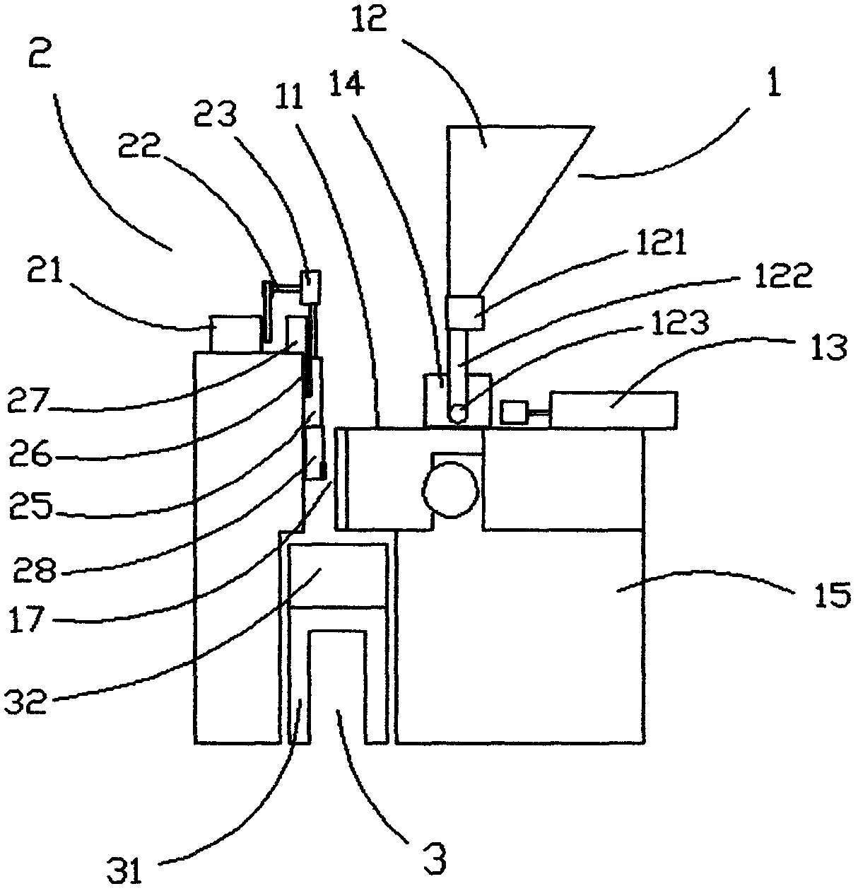
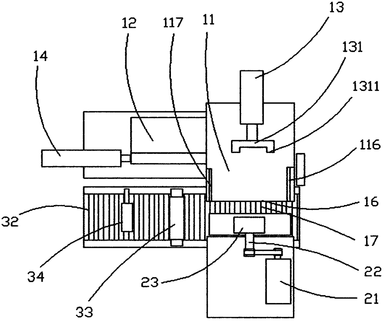
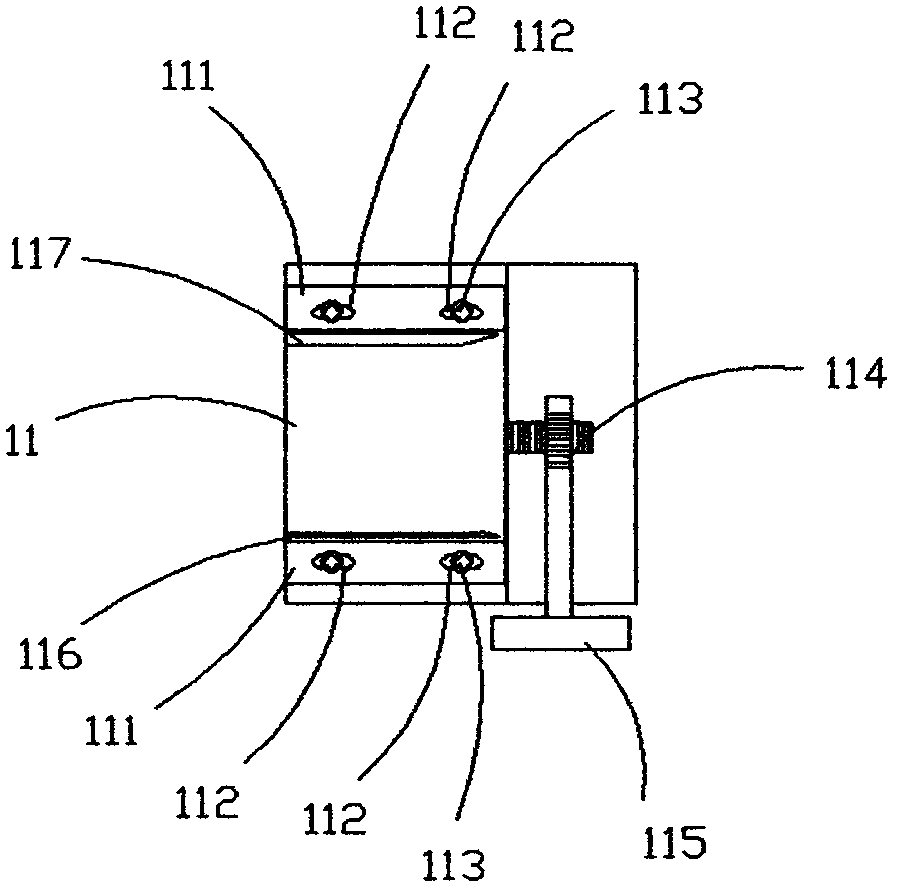
[0018] Such as figure 1 , 2 , 3, and 4, a small cylindrical workpiece marking machine includes a feeding device 1, a sliding pressure device 2, and a discharge mechanism 3. The base 15 of the feeding device 1 and the feeding table 11 are provided with two right-angled The power mechanism I13 and the power mechanism II14 installed, the power mechanism I13 and the power mechanism II14 of the present embodiment are cylinders. The top of the push rod of the power mechanism I13 is provided with a ∏-shaped push piece 131, and the two top surfaces 1311 of the push piece 131 are parallel to the sliding pressure surface 16 on the outside of the feeding table 11, and the bottom of the hopper 12 is provided with a distributor 121. The discharge hole 123 on both sides of the 122 mouth is on the same axis as the push rod of the power mechanism II14, and the both sides of the feeding platform 11 are provided with an adjustment stop 116 and a spring baffle 117, and the sliding pressure devi...


PUM


Abstract

A small cylinder workpiece imprinting machine comprises a feeding device, a sliding and pressing device and a discharging mechanism. A machine base feeding table of the feeding device is provided with a power mechanism I and a power mechanism II which are arranged in a right-angle manner. An n-shaped pushing piece is arranged at the top end of a push rod of the power mechanism I. A material distributor is arranged below a hopper. Discharging holes in the two sides of a discharging way opening and a push rod of the power mechanism II are located on the same axis. An adjusting butting block part and a spring baffle are arranged on the two sides of the feeding table. A sliding block of the sliding and pressing device is fixed into a guide rail of a machine base plate through a pressing plate. The motor drives an eccentric wheel on a spindle to rotate, a connecting rod of the eccentric wheel is connected with the sliding block, the lower portion of the sliding block is connected with a die head provided with a character die, the outer side face of the die head is parallel to the sliding and pressing face of the outer side of the feeding table, and a downward sliding groove is formed. The die head downwards moves under the action of the sliding block, and the character die conducts rolling on the surface of a cylinder workpiece in the downward sliding groove.

Description

technical field [0001] The invention relates to a device for printing on the surface of a workpiece, in particular to a small cylindrical workpiece marking machine. Background technique [0002] The specifications, trademarks, codes and other markings on the surface of the drill bit are currently stamped by hand. This method is labor-intensive, low in efficiency, and the fonts are of different depths, which affects the visual aesthetics and quality of the product. Someone once invented a fast cylindrical workpiece coding machine (notification number CN101774310), which includes a base, a main shaft, a type box and a type, a motor and a gearbox, a built-in motor and a gearbox in the base, and a type box clamp Tight font, install a circular feeding tray obliquely on the machine base, a baffle is installed on the rear side of the circular feeding tray, a bracket is fixedly obliquely installed on the machine base, the main shaft seat plate is installed on the support with adjust...

Claims


Application Information

Patent Timeline
Patent Type & Authority Patents(China)
IPC IPC(8): B41K3/20B41K3/62
CPCB41K3/20B41K3/62
Inventor 杨志平
Owner ANHUI HAODING METAL PROD LIMITED
Why Eureka
Try Eureka