
The connection structure of the modular smart ring and the modular smart ring

A connection structure and modular technology, applied in rings, clothing, jewelry, etc., can solve the problems of only standby, poor battery life, and unable to turn off the control system, so as to facilitate the replacement of batteries and increase the use time.

Active Publication Date: 2018-09-25
GUANGZHOU SHIYUAN ELECTRONICS CO LTD
View PDF5 Cites 0 Cited by
  • Summary
  • Abstract
  • Description
  • Claims
  • Application Information

AI Technical Summary

Problems solved by technology

[0002] At present, the function of the smart ring is relatively single, and it can only do some simple identification functions, which cannot meet the needs of users. Moreover, the existing smart ring cannot turn off the control system (only standby) when not wearing it, resulting in poor battery life. And it is difficult to replace the backup power supply

Method used


Image

  • The connection structure of the modular smart ring and the modular smart ring
  • The connection structure of the modular smart ring and the modular smart ring
  • The connection structure of the modular smart ring and the modular smart ring

Examples


Embodiment Construction

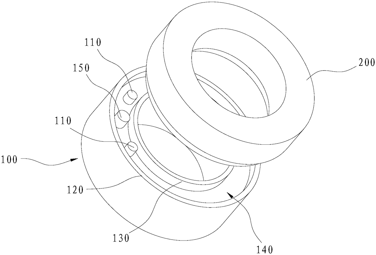
[0035] In order to make the object, technical solution and advantages of the present invention clearer, the present invention will be further described in detail below in conjunction with the accompanying drawings and specific implementation methods. It should be understood that the specific embodiments described here are only used to explain the present invention, and do not limit the protection scope of the present invention.

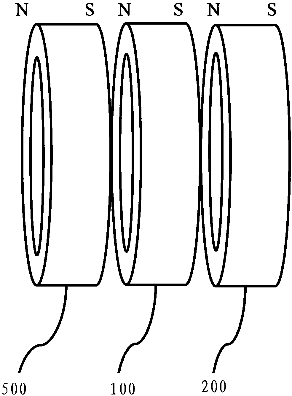
[0036] Such as figure 1 and 2 As shown, the connection structure of a modular smart ring according to the present invention includes a first ring-shaped housing 100, and a first metal bump 110 is provided at the end of the first ring-shaped housing 100; and a second ring shaped housing 200, the end of the second annular housing 200 is provided with a first fitting hole 210 matching with the first metal bump 110, and the inner wall of the first fitting hole 210 is provided with an electrical connection with the first metal bump 110. A first metal con...


PUM


Abstract

The invention relates to a modular intelligent ring connecting structure and a modular intelligent ring. The modular intelligent ring connecting structure comprises: a first annular shell, wherein the end portion of the first annular shell is provided with a first metal bump; and a second annular shell, wherein the end portion of the second annular shell is provided with a first mating hole fitting with the first metal bump, and the inner wall of the first mating hole is provided with a first metal wafer electrically connected with the first metal bump. The modular intelligent ring connecting structure is convenient for a user to select and connect different modules according to practical needs. The modular intelligent ring is convenient for selecting a functional module according to user's needs, and is also convenient for the user to replace a battery, so the service life of the intelligent ring is prolonged.

Description

technical field [0001] The invention relates to the technical field of smart wearable devices, in particular to a connection structure of a modular smart ring and the modular smart ring. Background technique [0002] At present, the function of the smart ring is relatively single, and it can only do some simple identification functions, which cannot meet the needs of users. Moreover, the existing smart ring cannot turn off the control system (only standby) when not wearing it, resulting in poor battery life. And it is difficult to replace the backup power supply. Contents of the invention [0003] Based on this, it is necessary to provide a connection structure of a modular smart ring and a modular smart ring, which are convenient for selecting functional modules according to user needs, and are convenient for users to replace batteries, thereby increasing the service life of the smart ring. [0004] Its technical scheme is as follows: [0005] A connection structure for...

Claims


Application Information

Patent Timeline
Patent Type & Authority Patents(China)
IPC IPC(8): A44C9/00
CPCA44C9/00A44C9/0053
Inventor 张享隆宋夏刘荣詹明东柯伟胜
Owner GUANGZHOU SHIYUAN ELECTRONICS CO LTD
Learn More