
A mobile power supply device for a trolley line

A technology for a mobile power supply and a trolley wire, which is applied in the field of movable power supply devices for trolley lines, can solve the problems of affecting the work efficiency, unable to set up a reliable temporary power supply box and other power supply devices, inconvenient maintenance workers, etc. Efficiency and reduced workload

Active Publication Date: 2019-02-22
SHANDONG IRON & STEEL CO LTD
View PDF8 Cites 0 Cited by
  • Summary
  • Abstract
  • Description
  • Claims
  • Application Information

AI Technical Summary

Problems solved by technology

[0004] At present, due to the restriction of harsh environmental factors such as large dust in the material yard and objective factors such as large area, when performing maintenance, repair and maintenance on the equipment under the jurisdiction of the area, it is impossible to install reliable temporary power boxes and other power supply devices in the area. For temporary power supply, power can only be taken from the power box near the power distribution room or on the large machine tool, and long-distance cable laying is carried out, and then a temporary power box is installed near the working position, and wiring is performed. The whole process brings great inconvenience to the maintenance workers Great inconvenience, seriously affecting work efficiency

Method used


Image

  • A mobile power supply device for a trolley line
  • A mobile power supply device for a trolley line
  • A mobile power supply device for a trolley line

Examples


Embodiment Construction

[0023] In order to clearly illustrate the technical features of the solution, the solution will be described below through specific implementation modes.

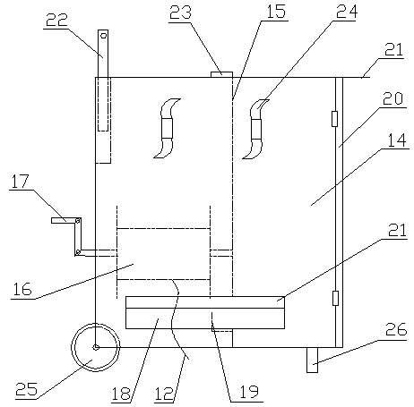
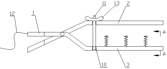
[0024] Such as figure 1 A movable power supply device for a trolley line is shown, including a power box 14 provided with a winding device, a power cable 12 wound on the winding device, and a power clip connected to the power cable 12 .

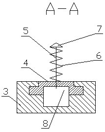
[0025] The power clamp includes an upper splint 2 and a lower splint 3 that are hinged to each other. The upper splint 2 and the lower splint 3 are insulating plates. One side of the hinge point of the upper and lower splints is provided with a tensioning device that pulls the upper splint 2 and the lower splint 3 relative to each other. , the end on the other side of the hinge point is respectively provided with a handle 1 with an insulating sheath, the lower splint 3 and the upper splint 2 are respectively provided with opposite and parallel straight sections, and the straight section an...


PUM


Abstract

The invention relates to a movable power supply device for a slide wire. The movable power supply device comprises a power box provided with a winding device, a power cable wound on the winding device, and a power clamp connected with the power cable. The power clamp comprises an upper clamping plate and a lower clamping plate which are hinged to each other. A tensioning device for pulling the upper clamping plate and the lower clamping plate oppositely is arranged on one side of the hinge point. A slide way is arranged on the side, provided with the tensioning device, of the hinge point and in the lower clamping plate. A plurality of slide supports are connected into the slide way in a sliding mode. A conductive rod extending to the upper clamping plate and connected with the power cable is fixedly arranged on each slide support. Contacts are fixedly arranged at the upper ends of the conductive rods. The large ground slide wire evenly distributed on the stock ground serves as the temporary power supply, the influences of the severe regional environment of the stock ground are eliminated, the workloads of operators are reduced, and work efficiency and temporary power utilization stability and safety are improved.

Description

technical field [0001] The invention relates to a power supply device for a trolley line for taking power temporarily, in particular to a movable power supply device for a trolley line. Background technique [0002] Sliding line is also called sliding line. It is a power supply system that feeds power to mobile mechanical equipment. It is mainly composed of aluminum alloy profile conductors and PVC insulating sheaths. It has a simple structure and is easy to install and maintain. It is widely used in mines, metallurgy , chemical industry and other industries. [0003] In the sintering raw material supply area of ​​the metallurgical industry, large-scale machinery and tools such as stackers and reclaimers, reclaimers, and stackers in the stockyard are used as the main equipment, and safety sliding contact wires are often used as low-voltage conductive forms. The safety sliding contact line generally adopts the HXPnR-H type single-stage combined sliding contact line. Due to ...

Claims


Application Information

Patent Timeline
Patent Type & Authority Patents(China)
IPC IPC(8): H02J4/00H02B1/46H02B1/52
CPCH02B1/46H02B1/52H02J4/00
Inventor 程昊
Owner SHANDONG IRON & STEEL CO LTD
Learn More