
Automatic control method for automatic screw feeding equipment

A screw, linear vibration technology, applied in metal processing equipment, manufacturing tools, metal processing and other directions, can solve problems such as equipment efficiency cannot be guaranteed, and achieve the effect of saving labor costs and improving production efficiency

Active Publication Date: 2018-02-13
华东泰克西汽车铸造有限公司
View PDF6 Cites 0 Cited by
  • Summary
  • Abstract
  • Description
  • Claims
  • Application Information

AI Technical Summary

Problems solved by technology

[0006] The speed of manual placement of the screw is affected by factors such as the physical condition, mood, and sense of responsibility of the workers on the day, and the efficiency of the equipment cannot be guaranteed.

Method used


Image

  • Automatic control method for automatic screw feeding equipment

Examples


Embodiment Construction

[0013] Below in conjunction with embodiment and accompanying drawing, the present invention will be further described.

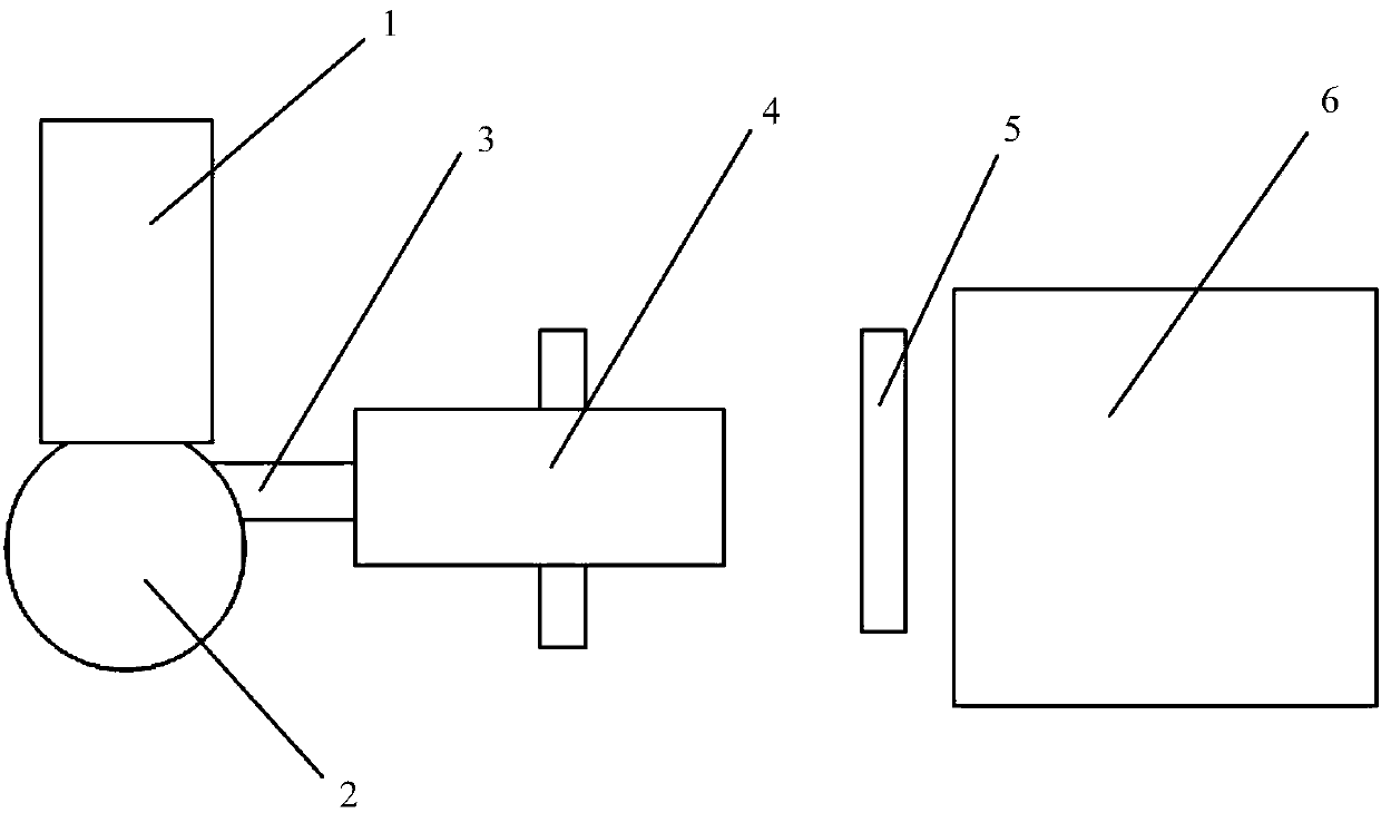
[0014] Such as figure 1 As shown, the present invention provides a kind of automatic control method of automatic screw rod equipment,

[0015] The automatic screw release equipment used in the method includes a feed bin 1, a disc conveying feeder 2, a linear vibrating guide rail 3, a pre-assembly mechanism 4, and a placement mechanism 5. The placing mechanism includes n jaw cylinders and two cylinders, one cylinder is used for the upward and downward movement of the jaw cylinder, and the other cylinder is used for the lateral movement of the jaw cylinder.

[0016] The silo 1 is transported to the disc conveying feeder 2 through the conveyor, and the linear vibrating guide rail 3 receives the screw from the exit of the disc conveying feeder 2; Line up on the vibrating guide rail 3.

[0017] Provide a pre-assembly mechanism 4 including pneumatic grippers th...


PUM


Abstract

The invention discloses an automatic control method for an automatic screw placing device. A bin is provided and conveyed to a disk feeder through a conveyor; a linear vibrating guide rail used for receiving screws at an outlet of the disk conveying feeder is provided; a pre-assembling mechanism is provided and used for grabbing the screws at an outlet of the linear vibrating guide rail, placing the screws in n pre-positioned positions according to different directions, and immediately leaving the pre-positioned positions after placing the screws well; and a placing mechanism is provided and used for descending to the pre-positioned positions from an initial position, grabbing n screws simultaneously, conveying the screws to a placing point, opening clamping jaws after moving in place to let the screws to fall to a corresponding position of a mould, and returning to the initial position. In the whole screw placing process, manual operation is not needed any more, the labor cost is reduced, and the production efficiency is improved.

Description

technical field [0001] The invention relates to the technical field of automatic control. Background technique [0002] When the core shooting machine is producing cylinder cores, in the current method used in the factory, it is necessary to stop the equipment before sand shooting, and place four screws into the mold for the core assembly needs of the subsequent process. Device reset. Each cycle of the equipment needs to repeat the above-mentioned work once. [0003] Existing problems and shortcomings: [0004] This work needs to be done by a special person, which is a waste of labor; [0005] Workers need to go up and down steps to complete the work, and there is a risk of slipping to cause work-related injuries; [0006] The speed of manually placing the screw is affected by factors such as the physical condition, mood, and sense of responsibility of the workers on the day, and the efficiency of the equipment cannot be guaranteed. [0007] Therefore, a new technical s...

Claims


Application Information

Patent Timeline
Patent Type & Authority Patents(China)
IPC IPC(8): B23P19/04
CPCB23P19/001B23P19/04
Inventor 徐晔解志坚张峻
Owner 华东泰克西汽车铸造有限公司
Learn More