
Mounting and positioning tool and mounting and positioning method for rear oil seal of engine crankshaft

A technology for installation and positioning of the engine, which is applied in the direction of manufacturing tools and hand tools, etc., can solve the problems of large concentricity error between the shaft hole of the rear end plate of the engine and the output gear of the crankshaft, and the inability to locate accurately, so as to reduce the difficulty of positioning and debugging, Save manpower and improve the effect of operating rate

Inactive Publication Date: 2016-12-07
ANSTEEL GRP MINING CO LTD
View PDF6 Cites 3 Cited by
  • Summary
  • Abstract
  • Description
  • Claims
  • Application Information

AI Technical Summary

Problems solved by technology

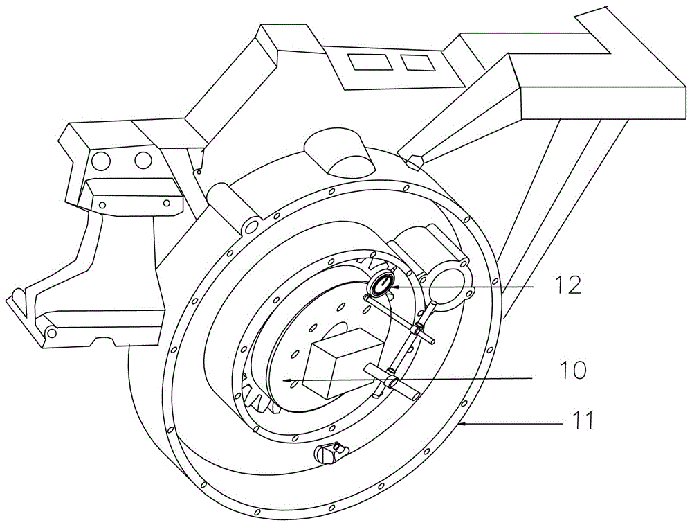
During the process of replacing the oil seal, there is no notch and positioning pin between the engine case and the rear end plate of the engine, so it cannot be positioned accurately. The original assembly process is as follows: figure 1 As shown, after installing the crankshaft output gear on the crankshaft eaves, install the rear end plate of the engine. When aligning the rear end plate of the engine, it is necessary to install a dial indicator on the output gear of the crankshaft, and then manually turn the crankshaft. According to the reading of the dial indicator To adjust the position of the rear end, it needs to be adjusted many times. Tighten the bolts immediately after the adjustment, and then turn the crankshaft. If the reading of the dial indicator exceeds the deviation range, you need to loosen the fixing bolts of the rear end plate and readjust until the deviation is within the allowable range. Within the range, the crankshaft rear oil seal can be installed
This requires the cooperation of multiple people and takes several hours to complete, and the concentricity error between the shaft hole of the rear end plate of the engine and the output gear of the crankshaft is relatively large

Method used


Image

  • Mounting and positioning tool and mounting and positioning method for rear oil seal of engine crankshaft
  • Mounting and positioning tool and mounting and positioning method for rear oil seal of engine crankshaft
  • Mounting and positioning tool and mounting and positioning method for rear oil seal of engine crankshaft

Examples


Embodiment Construction

[0024] The specific embodiments of the present invention are further described below with reference to the accompanying drawings.

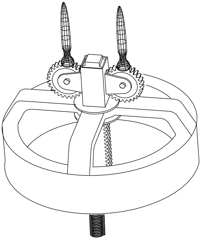
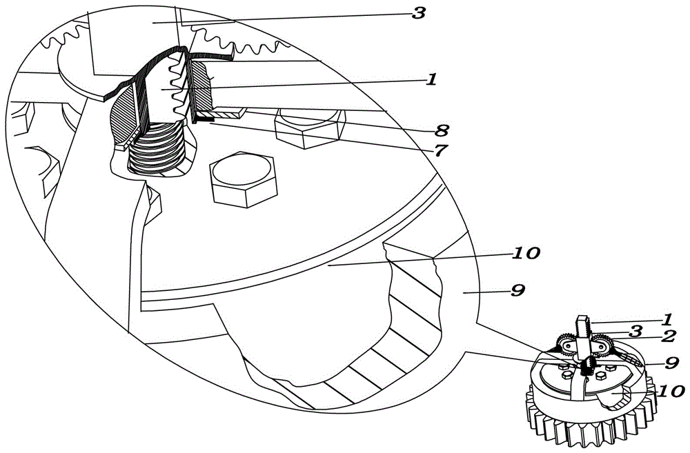
[0025] like figure 1 , 2 , 3 and 4, the engine crankshaft rear oil seal installation and positioning tool of the present invention is characterized in that it comprises a sliding sleeve 3 with a flange at the bottom, and the rectangular holes provided on both sides of the sliding sleeve 3 are provided in each rectangular The push gear support frame at the hole end, the push gear 2 set on each push gear support frame, the push gear rack 1 set in the sliding sleeve 3, the push gear rack 1 set on the sliding sleeve 3 protruding locating sleeve 9 on the edge,

[0026] The pushing rack 1 includes a rack 1-1 at the upper part and a screw 1-2 at the lower part, and each of the pushing gears 2 includes a gear 2-1 and is fixed on the gear 2-1 The handle 2-2, the gears 2-1 on the two push gears 2 respectively pass through the two rectangular holes and en...


PUM


Abstract

The invention belongs to the technical field of automobile maintenance tools, and particularly relates to a mounting and positioning tool and a mounting and positioning method for a rear oil seal of an engine crankshaft. The mounting and positioning tool for the rear oil seal of the engine crankshaft is characterized by comprising a slide sleeve with a flange on bottom, rectangular holes formed in the two sides of the slide sleeve, a pushing-pressing gear supporting frame arranged at each rectangular hole frame, a pushing-pressing gear separately arranged on each pushing-pressing gear supporting frame, a pushing-pressing rack arranged in the slide sleeve, and a positioning sleeve arranged on the flange of the slide sleeve. The mounting and positioning method is convenient and quick, so that mounting program is simplified, positioning and debugging difficulties are reduced, and an equipment operating rate is increased; waste of oil products, anti-freezing solutions and other materials is reduced, manpower and material and financial resources are saved, and cost is reduced; and when a plurality of workpieces are assembled, assembly can be completed once with high precision while aligning and debugging are not needed.

Description

technical field [0001] The invention belongs to the technical field of automobile maintenance tools, and in particular relates to an installation and positioning tool and an installation and positioning method for a rear oil seal of an engine crankshaft. Background technique [0002] Engines are the source of power for articulated mining trucks and excavators. During the operation, the seal between the connecting gear of the engine crankshaft and the rear end plate of the engine (hereinafter referred to as the rear oil seal of the crankshaft) often leaks lubricating oil, and the oil leakage is more obvious after running for more than 3000 hours. In the process of replacing the oil seal, there is no stop and positioning pin between the engine case and the rear end plate of the engine, so it cannot be accurately positioned. The original assembly process is as follows: figure 1 As shown in the figure, after installing the crankshaft output gear on the crankshaft eave, install ...

Claims


Application Information

Patent Timeline
IPC IPC(8): B25B27/06
CPCB25B27/06
Inventor 王大千喻绍俊马晓亮张子清刘启涛
Owner ANSTEEL GRP MINING CO LTD
Learn More