
Single-circle-rotation-actuated continuous spray distributor

A technology of actuators and actuating collars, applied in the direction of a single handheld device, spray device, liquid spray device, etc., can solve problems such as feasibility defects

Inactive Publication Date: 2016-11-23
ALTERNATIVE PACKAGING SOLUTIONS
View PDF9 Cites 3 Cited by
  • Summary
  • Abstract
  • Description
  • Claims
  • Application Information

AI Technical Summary

Problems solved by technology

All patents are deficient in the cost of commercial acceptance and feasibility of mass production at high levels in existing market applications

Method used


Image

  • Single-circle-rotation-actuated continuous spray distributor
  • Single-circle-rotation-actuated continuous spray distributor
  • Single-circle-rotation-actuated continuous spray distributor

Examples


Embodiment Construction

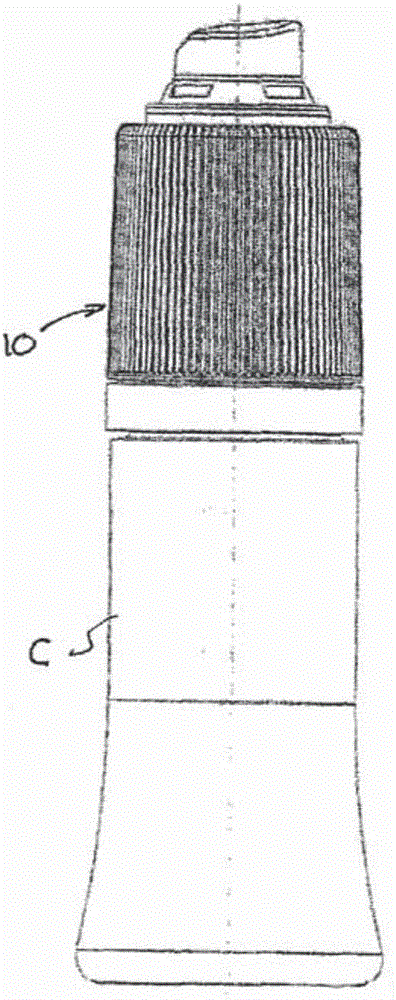
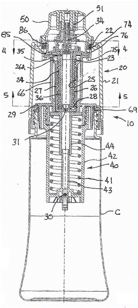
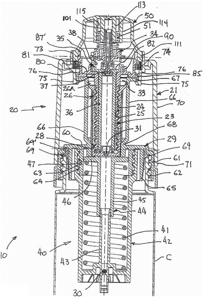
[0090] Figure 1-Figure 18 A first preferred embodiment of the invention is shown. In this form of the invention, an energy storage assembly 10 comprising a pump mechanism 20 and a spring mechanism 40 is mounted to a container C for dispensing product therefrom (not shown).

[0091] Such as Figure 1-Figure 7 , Figure 9A and Figure 9B As clearly shown in , the pump mechanism 20 includes a rotatable actuating collar 21 connected by an escapement 22 to a drive screw 23 having an externally threaded tubular shaft 24 that is connected to a hollow An internal thread 25 in a tubular piston 26 engages, the hollow tubular piston 26 having a sliding seal 26A at its upper end. Axial splines 27 on the outer surface of the piston engage mating axial splines 28 in a bell cylinder 29 mounted at the open upper end of the container C. The splines prevent the piston from rotating, causing the piston to move from image 3 The first non-operating position shown reciprocates to Figure 6...


PUM


Abstract

An energy storage assembly used for obtaining products continuously discharged out of a container comprises a pump mechanism, a bleed valve closed in the general state, an actuator and a drive device. The pump mechanism comprises a pump cylinder and a piston reciprocating in the pump cylinder. The drive device is connected with the piston and used for making the piston reciprocate from the non-working position in the first direction so that the products can be sucked to enter a pump chamber. The drive device comprises a rotatable actuation lantern ring, the actuator and a drive threaded rod. When the actuation lantern ring rotates, rotation of the drive threaded rod is caused by rotation of the actuation lantern ring so that the piston can reciprocate in the first direction; and when the piston moves in the first direction, an energy storage device is connected with the pump mechanism and used for storing energy, the energy storage device exerts pressure on the piston, and therefore the piston is moved in the second direction, and pressurization is conducted on the products in the pump chamber.

Description

[0001] This application is an international application submitted on April 11, 2012 and entered the Chinese national phase on October 11, 2014. The Chinese application number is 201280072333.4. Divisional application. technical field [0002] The present invention relates to dispensers, and more particularly to continuous spray dispensers, which are mechanically actuated and pressurized by non-chemical means. Background technique [0003] Both chemically actuated and mechanically operated spray dispensers have been in use for many years and are still widely used due to their convenience. However, aerosol dispensers using chemical propellants have come under increasing scrutiny and restrictions due to their environmental hazards, the dangers of their disposal, associated insurance costs, and the like. Furthermore, compared to chemically actuated aerosol dispensers, conventional non-chemical mechanical spray dispensers are disfavored due to their bulkiness and often multiple ...

Claims


Application Information

Patent Timeline
Patent Type & Authority Applications(China)
IPC IPC(8): B65D47/34
CPCB05B11/1002B05B11/1053B05B11/1059B05B11/1069B05B11/1074B05B9/0883
Inventor 威廉姆·悉尼·布莱克
Owner ALTERNATIVE PACKAGING SOLUTIONS
Learn More