
A subframe installation point structure

A subframe and installation point technology, applied in the substructure, vehicle parts, transportation and packaging, etc., can solve the problems such as difficult subframe detachment, large vibration of the subframe body, and influence of modal stiffness, etc., to achieve Ease of installation and assembly and modular production, improve handling stability and reduce injuries

Active Publication Date: 2018-02-16
CHERY AUTOMOBILE CO LTD
View PDF6 Cites 1 Cited by
  • Summary
  • Abstract
  • Description
  • Claims
  • Application Information

AI Technical Summary

Problems solved by technology

However, for the hard-connected subframe, the connection rigidity is high, and it is difficult to realize the detachment of the subframe during a collision. If the rigidity of the installation point of the hard-connected subframe is reduced, it will affect the The modal stiffness of the subframe is affected, which can easily cause the vibration of the sub-frame body to be relatively large, which in turn leads to the roaring sound in the cockpit

Method used


Image

  • A subframe installation point structure
  • A subframe installation point structure
  • A subframe installation point structure

Examples


Embodiment 1

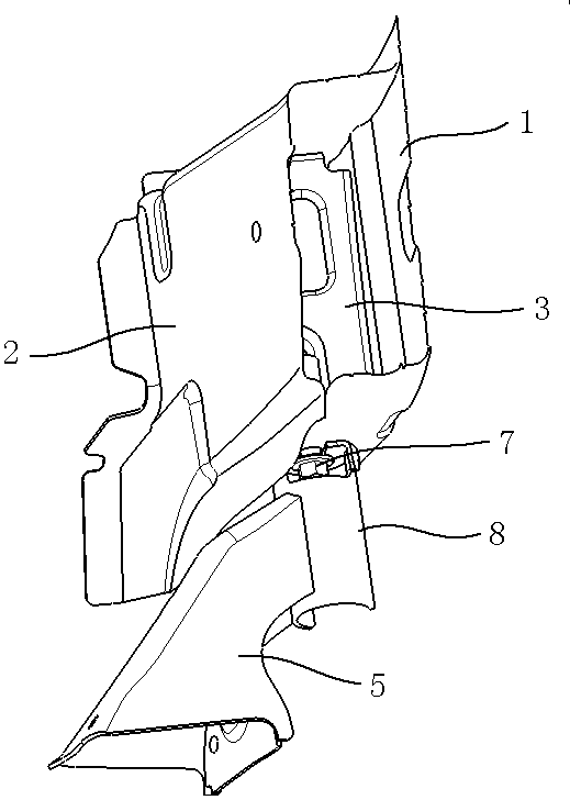
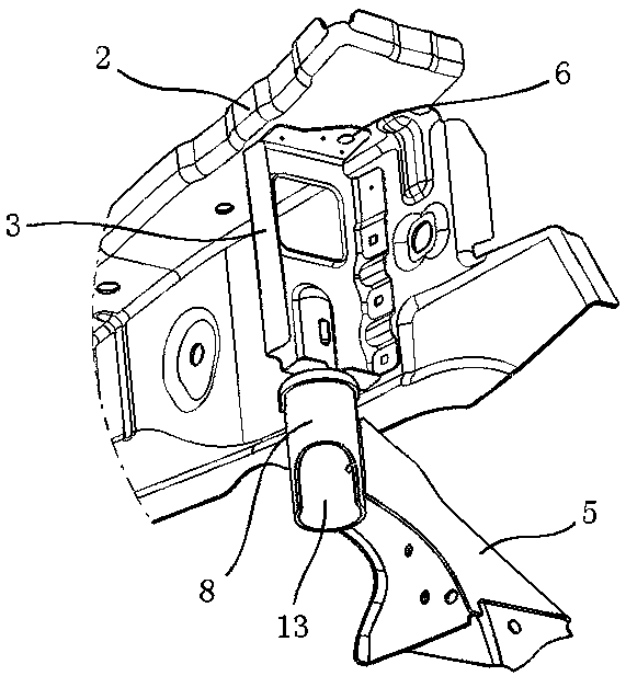
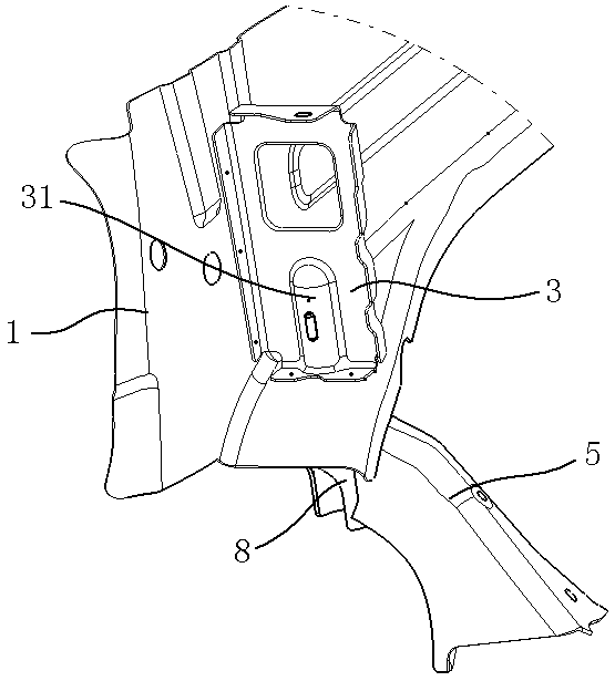
[0023] As shown in the figure, the mounting point structure of the sub-frame in this embodiment includes: a longitudinal beam composed of an outer plate 1, an inner plate 2 and a reinforcing plate 3, an internally threaded sleeve 4, and a sub-frame provided with a mounting support 5, of which:

[0024] The outer plate 1 and the inner plate 2 are welded and connected to form a cavity structure with a frame-shaped closed section. The reinforcement plate 3 is located at the rear end of the longitudinal beam, and there are flanges around the reinforcement plate 3. The reinforcement plate 3 is located in the cavity. The flanges on the left, right and upper and lower sides are overlapped with the inner panel 2 and outer panel 1 of the longitudinal beam, which are used to increase the dynamic stiffness of the installation point of the subframe 5 and ensure the modal stiffness of the subframe 5 when it is installed in the body state ; Specifically, as figure 2 As shown, the upper pa...


PUM


Abstract

The invention aims at providing an auxiliary frame mounting point structure. The auxiliary frame mounting point structure can realize drop in a collision process and reduce harm on a passenger in a passenger compartment. The auxiliary frame mounting point structure comprises an auxiliary frame provided with a mounting support and a longitudinal beam. The auxiliary frame mounting point structure is characterized inthat an internal screw thread sleeve with the bottom end open is fixed on the longitudinal beam; the mounting support is composed of a tubular support body with the two ends open and a cap body fixedly arranged at the top end of the support body, gaps corresponding in position are formed in the front end of the cap body and the front end of the upper part of the support body, a guide slot connected with the gaps is formed in the cap body, and the guide slot extends along the length direction of an automobile; and the auxiliary frame is fixedly connected with the longitudinal beam by utilizing a bolt which penetrates through the support body and the cap body and is screwed into the internal screw thread sleeve, and an anti-drop part with the diameter larger than the width of the guide slot is arranged at the bottom end of the bolt. The auxiliary frame mounting point structure has the advantages that the auxiliary frame can drop in the collision process and harm done to a passenger can be reduced.

Description

technical field [0001] The invention relates to the technical field of automobile structure design, more specifically, the invention relates to a sub-frame mounting point structure. Background technique [0002] As an important part of the load-bearing car chassis, the sub-frame mainly has the following functions: to realize the connection between the suspension and the body through the sub-frame; to support the steering gear assembly; to install the rear suspension of the powertrain; stiffness. The connection points between the subframe and the body are divided into two types: hard connection and soft connection. The hard connection is to directly fix the subframe on the body through the inner threaded sleeve of the bolt. The connection rigidity is very large, which is beneficial to handling, but not conducive to Vibration attenuation; the soft connection is to connect the sub-frame and the body through a rubber bush with a certain rigidity. This type of connection has a r...

Claims


Application Information

Patent Timeline
Patent Type & Authority Patents(China)
IPC IPC(8): B62D21/00B62D21/02
CPCB62D21/00B62D21/02
Inventor 王梁
Owner CHERY AUTOMOBILE CO LTD
Learn More