Preloading device for force measuring device

A force measuring device and force sensor technology, applied in the direction of measuring device, force sensor in the hole of the force-bearing structure, and the measurement of the property force of the piezoelectric device, can solve the problems of cumbersome fixing, etc., to prevent interference clamping effect

Inactive Publication Date: 2019-08-20
KISTLER HLDG AG
View PDF9 Cites 0 Cited by
  • Summary
  • Abstract
  • Description
  • Claims
  • Application Information

AI Technical Summary

Problems solved by technology

[0005] The pretensioning devices or force-measuring devices known from the prior art, which include pretensioning devices with integrated force sensors, are composed of several parts and can only be screwed in cumbersomely with the aid of a screwing tool. Screwed and pre-tightened between differently shaped recessed walls

Method used


Image

  • Preloading device for force measuring device
  • Preloading device for force measuring device
  • Preloading device for force measuring device

Examples


Embodiment Construction

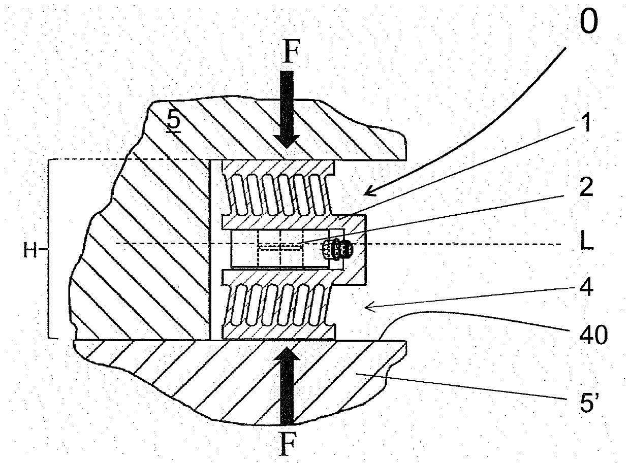
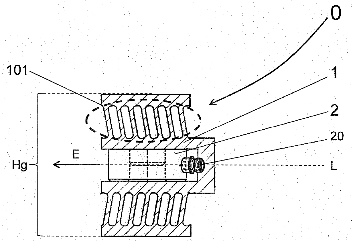
[0017] exist figure 1 A force measuring device 0 is shown in , which comprises a pretensioning device 1 and a force sensor 2 . In this case, the pretensioning device 1 is produced in one piece and inserted into the recess 4 between the two machine components 5 , 5 ′, where it is releasably clamped. The cutout 4 is formed by a planar cutout wall 40 , where the distance of the pretensioning device 1 in the direction of force transmission, characterized by a force F acting perpendicular to the longitudinal direction L, corresponds to its installation in elastic tension. State height H. The pretensioning of the pretensioning device 1 is structurally limited, since the pretensioning device 1 is elastically bendable within a defined range and can thus be introduced into the cutout 4 and can be positioned there relative to the cutout wall. 40 is held clampingly. The force F acting on the machine component 5 , 5 ′ transversely to the longitudinal axis L and thus in the clamping dir...


PUM


Abstract

The invention relates to a pretensioning device (1), which has a receiving recess (11) for accommodating a force sensor, the pretensioning device can be arranged in a machine component, or between a plurality of machine components, or The pretensioning device can be placed flexibly and easily in differently shaped recesses and can be fixed easily and releasably in the recesses in the roll. This can be achieved as follows: the pretensioning device (1) has a tool grip section (12) spaced apart from the receiving recess (11) in the direction of the longitudinal axis (L), and at least one elastically bendable section ( 101) is non-detachably arranged between the receiving recess (11) and at least one force-transmitting plate (100), wherein, through the elastic bending of at least one elastically bendable section (101) and through Various directions of the axis (L) exert forces on the at least one force-transmitting plate (100, 100') and the tool gripping section (12), enabling the height of the pretensioning device (1) to be lowered from the relaxed state to the introduced state down height.

Description

technical field [0001] The invention relates to a pretensioning device, which has a receiving recess for accommodating a force sensor, the pretensioning device comprising at least two force transmission plates arranged opposite each other in a direction perpendicular to the longitudinal axis, said force transmission plates having a mutual Force-transmitting surface facing away; the invention also relates to a force-measuring device and a device for introducing the force-measuring device into a cavity in a machine component, or between several machine components, or in a roller. method. Background technique [0002] Force-measuring devices have been known for a long time in various embodiments, including pretensioning devices for clamping force sensors. Such a force measuring device can measure dynamic and quasi-static forces applied in at least one spatial direction. Preference is given to using piezoelectric force sensors, in most cases so-called piezoelectric measuring w...

Claims


Application Information

Patent Timeline
Patent Type & Authority Patents(China)
IPC IPC(8): G01L5/00
CPCG01L5/0004G01L1/16G01L5/0028
Inventor 罗尔夫·蒂尔
Owner KISTLER HLDG AG
Why Eureka
Try Eureka