Device for replacing permanent-magnet circuit breaker controller in charged mode
A permanent magnet circuit breaker, live replacement technology, applied in the direction of switchgear, electrical components, protective switch terminals/connections, etc., can solve the problems that affect the economic benefits of enterprises, reduce the reliability of power supply, and the loss of power users, so as to avoid personal injury and equipment accidents, reducing downtime, and preventing power outages
- Summary
- Abstract
- Description
- Claims
- Application Information
AI Technical Summary
Problems solved by technology
Method used
Image
Examples
Embodiment 1
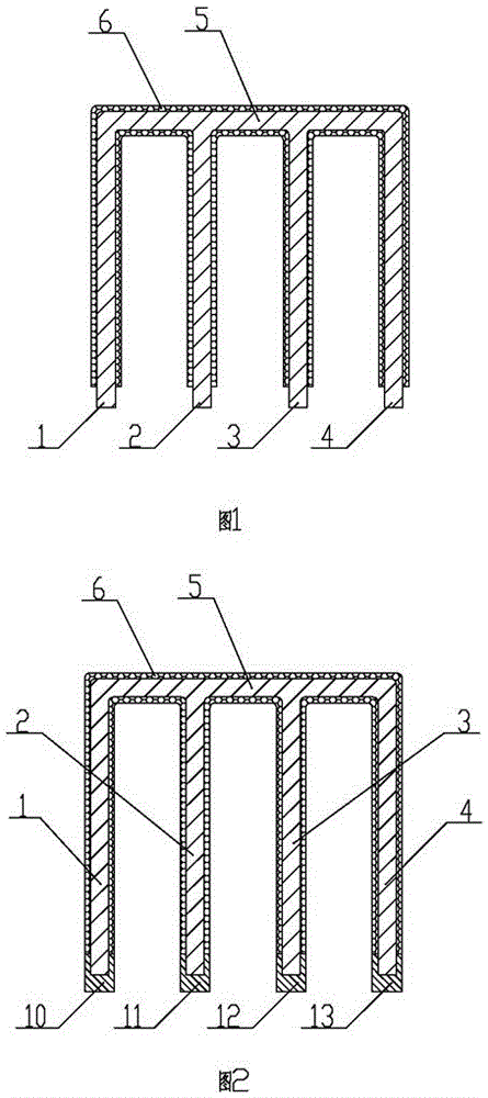
[0019] Embodiment one: as attached figure 1 , 2 As shown, the device for replacing the permanent magnet circuit breaker controller with electricity includes a first plug 1, a second plug 2, a third plug 3, a fourth plug 4 and a connecting guide rod 5, the upper end of the first plug 1, the second plug The upper end of 2, the upper end of the third plug 3, and the upper end of the fourth plug 4 are respectively fixedly installed on the connecting guide rod 5 and electrically connected with the connecting guide rod 5. This embodiment includes a connecting guide rod 5 and four plugs. When the controller 9 needs to be replaced, the first plug 1, the second plug 2, the third plug 3, and the fourth plug 4 are respectively inserted into the first terminal 10, In the second terminal 11, the third terminal 12, and the fourth terminal 13, the current loop of the controller 9 is disconnected, and then the controller 9 is powered off, and the controller 9 can be replaced, realizing the l...
Embodiment 2
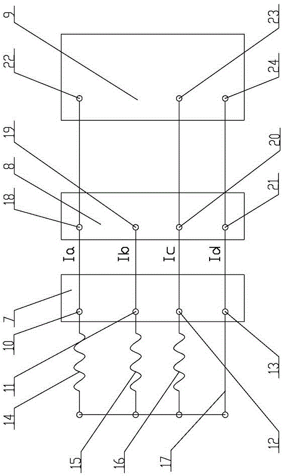
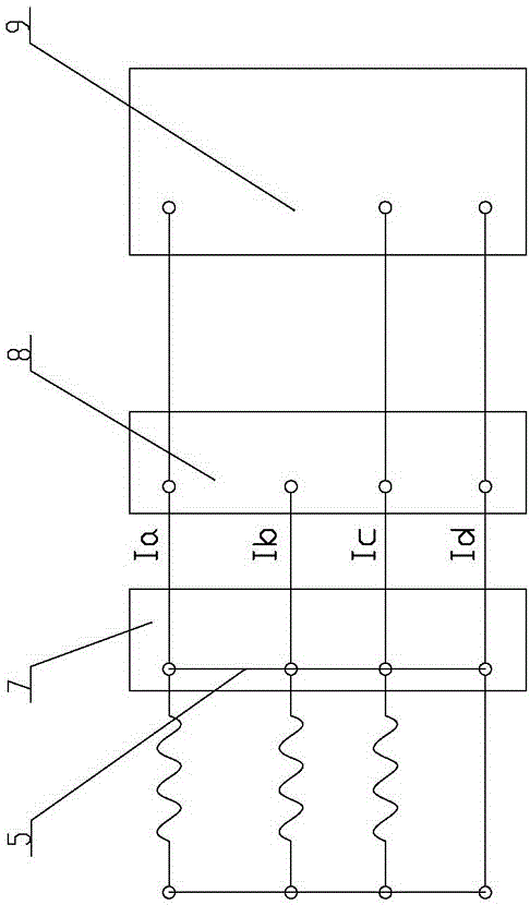
[0023] Embodiment two: as attached image 3 , 4 As shown in , 5, the above-mentioned device for replacing the permanent magnet circuit breaker controller with power also includes a control aviation terminal 7, a control box unit terminal block 8, and a controller 9, and the control aviation terminal 7 is provided with a first terminal 10 and a second terminal 11 , the third terminal 12, the fourth terminal 13, the input end of the first terminal 10 is connected with the A-phase current transformer 14, the input end of the second terminal 11 is connected with the B-phase current transformer 15, the input end of the third terminal 12 A C-phase current transformer 16 is connected, and the input end of the fourth terminal 13 is connected with the first common line 17; the control box unit terminal row 8 is provided with the fifth terminal 18, the sixth terminal 19, the seventh terminal 20 and the eighth terminal Terminal 21, the first terminal 10 is electrically connected to the ...
PUM
 Abstract
Description
Claims
Application Information
 - R&D
- Intellectual Property
- Life Sciences
- Materials
- Tech Scout
- Unparalleled Data Quality
- Higher Quality Content
- 60% Fewer Hallucinations
Browse by: Latest US Patents, China's latest patents, Technical Efficacy Thesaurus, Application Domain, Technology Topic, Popular Technical Reports.
© 2025 PatSnap. All rights reserved.Legal|Privacy policy|Modern Slavery Act Transparency Statement|Sitemap|About US| Contact US: help@patsnap.com


