An automatic capping mechanism for electronic connectors

A technology for electronic connectors and caps, which is applied to electrical components, electrical components, etc., and can solve problems such as automatic capping of end caps and electronic connectors

Active Publication Date: 2022-02-15
SUZHOU JUNCHANG COMM TECH CO LTD
View PDF12 Cites 0 Cited by
  • Summary
  • Abstract
  • Description
  • Claims
  • Application Information

AI Technical Summary

Problems solved by technology

At present, there is no mechanism for automatic capping of end caps and electronic connectors

Method used


Image

  • An automatic capping mechanism for electronic connectors
  • An automatic capping mechanism for electronic connectors
  • An automatic capping mechanism for electronic connectors

Examples


Embodiment Construction

[0022] The present invention will be described in further detail below through specific examples.

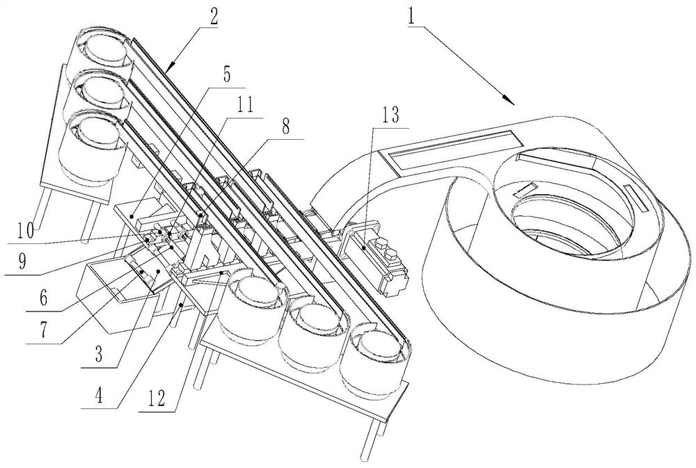
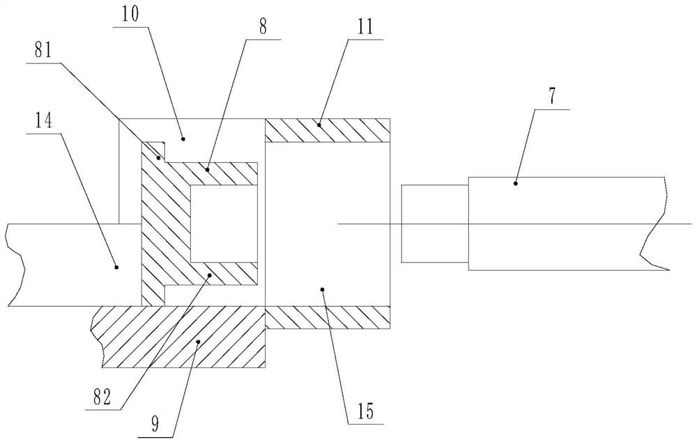
[0023] Such as Figure 1 to Figure 3 As shown, an automatic capping mechanism for electronic connectors, the automatic capping mechanism can cooperate with the automatic feeding mechanism 1 for electronic connectors and the automatic feeding mechanism 2 for end caps. Such as figure 1 and figure 2 As shown, the automatic capping mechanism includes a frame 4, the frame 4 is provided with a capping platform 5, and the frame 4 is equipped with a circulating conveyor belt 3 driven by a circulating power unit 13, and the circulating conveyor belt 3 is installed on the frame 4. The power unit 13 is driven by a motor.

[0024] The belt surface of the endless conveyor belt 3 is provided with several feeding slots 6 for embedded electronic connectors 7 at intervals, and the feeding slots 6 are evenly spaced on the belt surface of the endless conveyor belt 3. The section of the slot 6...


PUM


Abstract

The invention discloses an automatic capping mechanism for electronic connectors, which comprises a frame, a capping platform is arranged on the frame, a circulating conveyor belt driven by a circulating power device is installed on the frame, and the belt of the circulating conveyor belt is There are several feeding card slots arranged at intervals on the surface, and the extending direction of the feeding card slots is perpendicular to the conveying direction of the conveyor belt. Bases are provided on both sides of the circulating conveyor belt on the cover platform, and several feeding slots are arranged on the base to stay on the conveyor belt. The positions of the feeding slots of the capping station match the end cap slots one by one. The capping platform is equipped with a capping mechanism. The automatic capping mechanism also includes an intelligent control device. The intelligent control device controls the cycle power device to drive the cycle conveyor belt intermittently. Continuous operation makes the feeding card slot on the endless conveyor belt stay at the capping station. The automatic capping mechanism can realize the automatic assembly of the end cap and the electronic connector, which greatly improves the efficiency and reduces the cost.

Description

technical field [0001] The invention relates to an automatic capping mechanism, in particular to an automatic capping mechanism for electronic connectors. Background technique [0002] Electronic connectors need to be heat treated during the manufacturing process, and the end of the electronic connector has several axial groove structures. Therefore, in order to reduce the deformation of the end of the electronic connector during heat treatment, it is necessary to The two ends of the connector are equipped with an end cap to limit the deformation of the end, so that the specifications of the electronic connector after heat treatment meet the requirements, and the qualified rate of the product is higher. However, there is no automatic capping equipment for electronic connectors at present. The end caps are placed on both ends of the electronic connectors through a large number of manual operations. The labor intensity is high, the labor cost is high, and it is difficult to co...

Claims


Application Information

Patent Timeline
Patent Type & Authority Patents(China)
IPC IPC(8): H05K13/04
CPCH05K13/0417
Inventor 吴文周加茹王丽
Owner SUZHOU JUNCHANG COMM TECH CO LTD
Why Eureka
Try Eureka