
Cable reeling device and elevating antenna system provided with the same

A cable reel and antenna system technology, applied to antennas, antenna parts, antenna supports/installation devices, etc., can solve the problems of troublesome finishing, low efficiency, waste of manpower, etc., and achieve the effect of simple operation and high efficiency

Active Publication Date: 2016-11-09
深圳市偲诺电子科技有限公司
View PDF8 Cites 3 Cited by
  • Summary
  • Abstract
  • Description
  • Claims
  • Application Information

AI Technical Summary

Problems solved by technology

[0003] The lifting antenna system usually includes a mast that can be lifted electrically or pneumatically, an antenna system on the top of the lifting mast, and a cable connected to the antenna system. , the cables are scattered on the ground in a disorderly manner, and the cables need to be rearranged artificially, and because the cables are too long, they are often wound together, and it is quite troublesome to arrange, which is a waste of manpower and very inefficient

Method used


Image

  • Cable reeling device and elevating antenna system provided with the same
  • Cable reeling device and elevating antenna system provided with the same
  • Cable reeling device and elevating antenna system provided with the same

Examples


Embodiment Construction

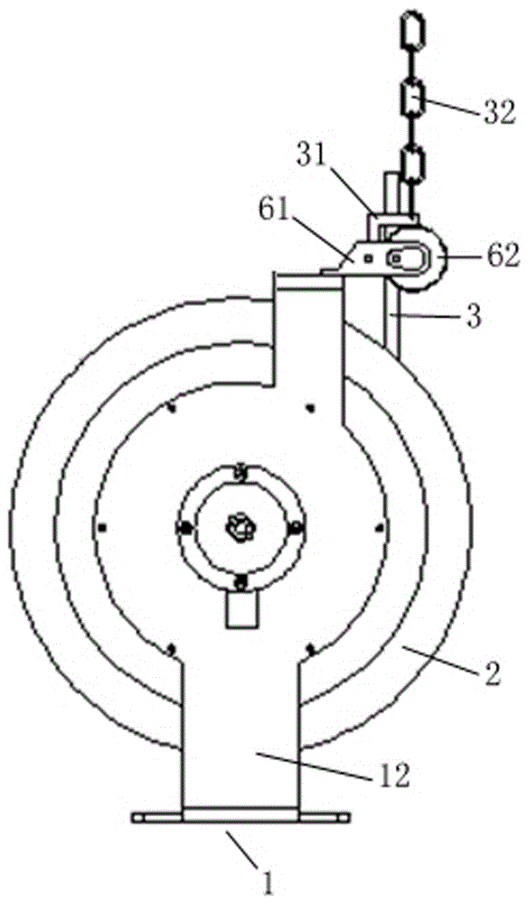
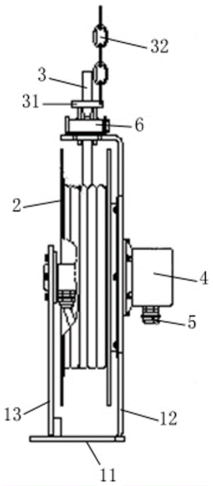
[0024] Such as figure 1 , 2 As shown, the cable reel device proposed by the present invention includes: a fixing mechanism 1, a winding reel 2, a cable 3 and the like.

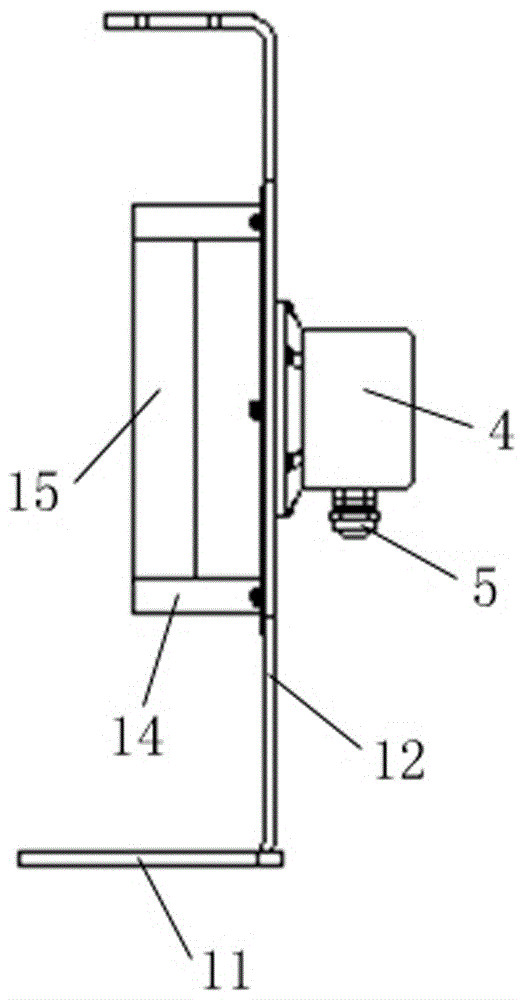
[0025] Such as figure 2 , 3 As shown, the fixing mechanism 1 is used to install and fix the winding reel 2, and mainly includes: a base plate 11, a front support plate 12 and a rear support plate 13 fixed on the base plate 11, between the front support plate 12 and the rear support plate 13 The coil spring device, the front support plate 12 and the rear support plate 13 are parallel and facing oppositely, the coil spring device is composed of the shell 14 and at least one coil spring 15 located at the shell 14, and the outer end of the coil spring 15 is fixed on the shell 14.

[0026] Such as Figure 4 As shown, the winding reel 2 is located between the front support plate 12 and the rear support plate 13, and it is composed of a bobbin 21 and two baffles 22 fixed at both ends of the bobbin 21, and the ca...


PUM


Abstract

The invention discloses a cable reeling device. The cable reeling device comprises a fixing mechanism, a wire spool disposed on the fixing mechanism, and a cable reeled on the wire spool orderly along one direction. The fixing mechanism comprises a bottom plate, two supporting plates, and a spring winding device. The wire spool is disposed between the two supporting plates, and the central position of the wire spool is provided with an inner shaft, which penetrates the two ends of the wire spool. The wire spool is disposed on the spring winding device in a sleeved manner, and the inner shaft passes through the spring winding device, and the inner side is provided with a rotating joint, and in addition, the inner end of the cable is electrically connected with one end of the rotating joint. The invention also provides an elevating antenna system provided with the cable reeling device. The function of the automatic folding and unfolding of the cable is realized, and therefore operation is simple, and the folding and unfolding efficiency is high.

Description

technical field [0001] The invention relates to the technical field of antenna equipment, in particular to a cable reel device and a lifting antenna system. Background technique [0002] An antenna is a converter that converts the guided wave propagating on the transmission line into an electromagnetic wave propagating in an unbounded medium, or vice versa, and is used in radio equipment to transmit or receive electromagnetic waves. At present, it is used in public security, fire protection, communication and military fields, such as the lifting antenna system installed on satellite news gathering vehicles, OB vehicles, military, public security command vehicles and other special vehicles. [0003] The lifting antenna system usually includes an electric or pneumatic lifting mast, an antenna system on the top of the lifting mast, and a cable connected to the antenna system. , the cables are scattered on the ground in a disorderly manner, and the cables need to be rearranged ...

Claims


Application Information

Patent Timeline
Patent Type & Authority Applications(China)
IPC IPC(8): H01Q1/00H01Q1/12
CPCH01Q1/00H01Q1/12
Inventor 白韵
Owner 深圳市偲诺电子科技有限公司
Learn More