
Screening device for producing refractory material

A screening device and a technology for refractory materials, applied in the field of machinery, can solve the problems of poor quality, low screening efficiency, and inability to meet the needs of refractory materials, and achieve the effect of meeting the needs of use and improving the screening effect.

Active Publication Date: 2016-11-09
新疆天山建材集团耐火材料有限责任公司
View PDF9 Cites 21 Cited by
  • Summary
  • Abstract
  • Description
  • Claims
  • Application Information

AI Technical Summary

Problems solved by technology

[0002] Screening operation is an indispensable part of refractory material production. There are many types of screening equipment in refractory material factories. Generally, there are two types of fixed sieves and movable sieves. The moving sieves mainly include shaking sieves, rotary sieves and vibrating sieves according to their movement modes. Due to the simple structure, high screening efficiency and strong production capacity, the vibrating screen is the most widely used, but in the existing screening device, for example, the utility model patent with the application number It is rotatably installed on the bracket. The screen drum includes a screen and two side plates. The screen is rolled into a cylindrical shape and has two openings on both sides. The two side plates are respectively fixed at the two openings of the screen and closed. Opening, although the patent has a certain screening function, but in actual use, the screening efficiency is low, and the quality of the screened is poor, which cannot meet the needs of refractory materials

Method used


Image

  • Screening device for producing refractory material
  • Screening device for producing refractory material

Examples


Embodiment Construction

[0013] The following will clearly and completely describe the technical solutions in the embodiments of the present invention with reference to the accompanying drawings in the embodiments of the present invention. Obviously, the described embodiments are only some, not all, embodiments of the present invention. Based on the embodiments of the present invention, all other embodiments obtained by persons of ordinary skill in the art without making creative efforts belong to the protection scope of the present invention.

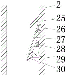
[0014] see Figure 1-2 , the present invention provides a technical solution: a screening device for producing refractory materials, including a casing 7, the top of the casing 7 is provided with a storage bin 6, and the inside of the storage bin 6 is provided with a buffer plate 1, so The inside of the buffer plate 1 is provided with a through hole 3. By setting the buffer plate 1, the potential energy of the raw material falling into the storage bin 6 is pre...


PUM


Abstract

The invention discloses a screening device for producing a refractory material. The screening device comprises a shell. A storage bin is arranged at the top end of the shell. A first screen frame is arranged at the top end in the shell, a coarse screen is fixedly installed at the upper end of the inner side of the first screen frame, and a fine screen is fixedly installed at the lower end of the inner side of the first screen frame. A second screen frame is arranged at the bottom end in the shell, an efficient screen is arranged on the inner side of the second screen frame, and a rotary cam is arranged at the bottom end of a drive motor. According to the screening device for producing the refractory material, through cooperation of the coarse screen, the fine screen and the efficient screen, an exciter works to drive the first screen frame to vibrate through a first vibrating spring and a first telescopic supporting rod; through cooperation of the coarse screen and the fine screen, the material is screened twice, and the screening effect is improved; and the drive motor works to drive a propelling ring groove through the rotary cam to drive the second screen frame to work in a reciprocating manner so that the efficient screen can finely screen the material, the screening effect is improved, and the use requirements of the refractory material are met.

Description

technical field [0001] The invention relates to the field of mechanical technology, in particular to a screening device for producing refractory materials. Background technique [0002] Screening operation is an indispensable part of refractory material production. There are many types of screening equipment in refractory material factories. Generally, there are two types of fixed sieves and movable sieves. The moving sieves mainly include shaking sieves, rotary sieves and vibrating sieves according to their movement modes. Due to the simple structure, high screening efficiency and strong production capacity, the vibrating screen is the most widely used, but in the existing screening device, for example, the utility model patent with the application number It is rotatably installed on the bracket. The screen drum includes a screen and two side plates. The screen is rolled into a cylindrical shape and has two openings on both sides. The two side plates are respectively fixed ...

Claims


Application Information

Patent Timeline
Patent Type & Authority Applications(China)
IPC IPC(8): B07B1/32B07B1/42B07B1/46
CPCB07B1/30B07B1/42B07B1/4609B07B1/4663B07B2201/02B07B2201/04
Inventor 佘云锋佘成其
Owner 新疆天山建材集团耐火材料有限责任公司
Learn More