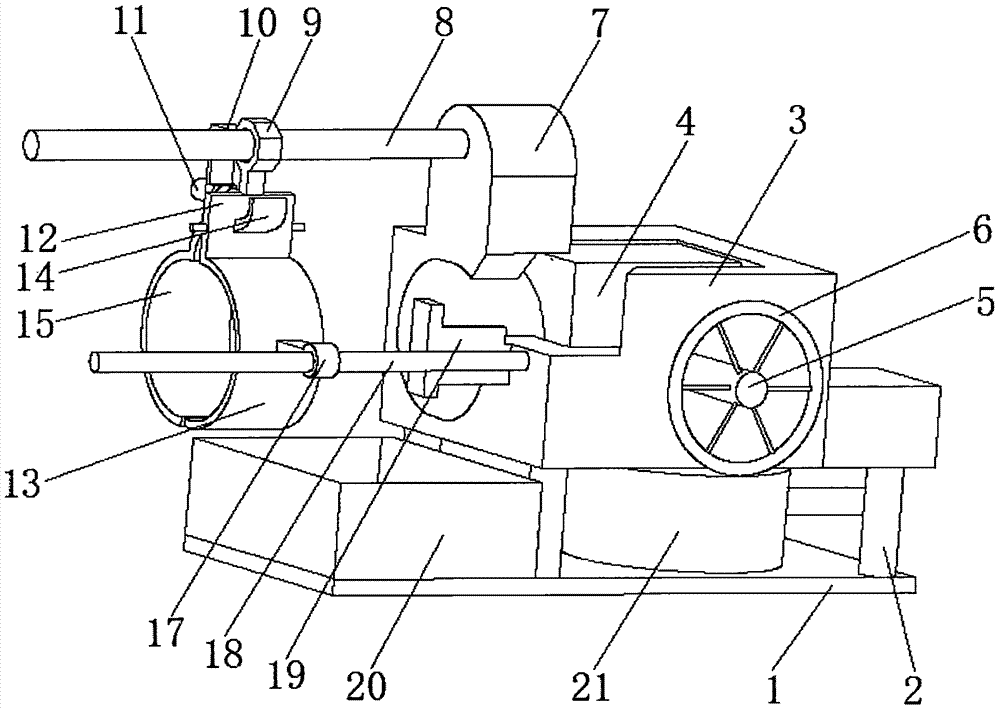
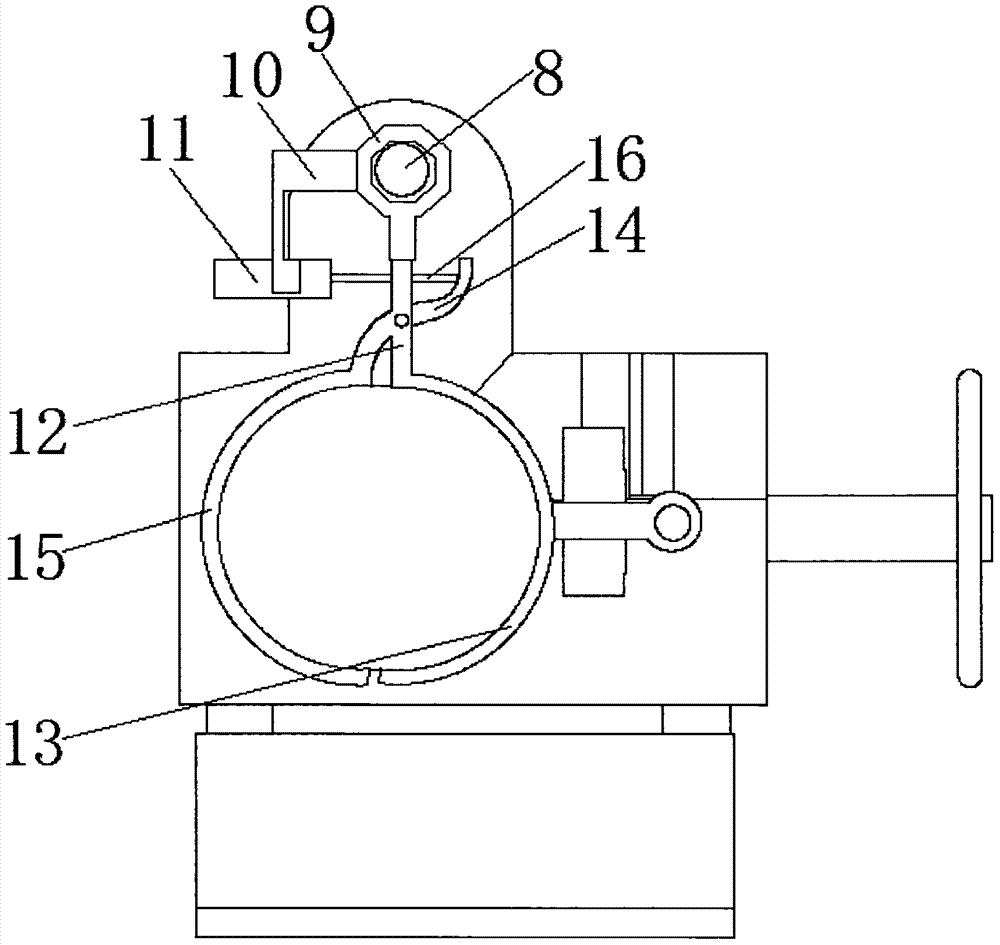
A mechanical automatic cutting machine

A cutting machine, mechanical technology, applied in metal processing and other directions, can solve the problems of inability to achieve production, rough end face, poor precision, etc., and achieve the effect of neat processing surface and strong stability

Inactive Publication Date: 2017-09-29
李培和
View PDF6 Cites 0 Cited by
  • Summary
  • Abstract
  • Description
  • Claims
  • Application Information

AI Technical Summary

Problems solved by technology

[0002] After the pipeline is produced, it is a whole long tube. It is necessary to cut a whole tube into multiple tubes of a specific length according to customer requirements. The traditional method of cutting by hand tools is not only inefficient, but also poor in accuracy. It cannot meet the requirements of production. Therefore, it is necessary to design a fully functional hose cutting machine and design a corresponding cutting mechanism. Generally, the hose is cut by a disc saw, and the end surface is relatively rough, while some cutting tools that are lifted and cut are directly set on the At the same time, the clamping device is not stable enough and the effect is poor. Therefore, we propose a mechanical automatic cutting machine

Method used


Image

  • A mechanical automatic cutting machine
  • A mechanical automatic cutting machine

Examples


Embodiment Construction

[0012] The following will clearly and completely describe the technical solutions in the embodiments of the present invention with reference to the accompanying drawings in the embodiments of the present invention. Obviously, the described embodiments are only some, not all, embodiments of the present invention. Based on the embodiments of the present invention, all other embodiments obtained by persons of ordinary skill in the art without making creative efforts belong to the protection scope of the present invention.

[0013] see Figure 1-2 , the present invention provides a technical solution: a mechanical automatic cutting machine, including a base plate 1, a support rod 2 is provided on the upper surface of the right end of the base plate 1, a clamping seat 3 is provided at the upper end of the support rod 2, and the clamping seat 3 An elliptical through hole is provided in the horizontal direction, a square groove is provided in the vertical direction of the clamping se...


PUM


Abstract

The invention discloses a mechanical automatic cutting machine which comprises a base plate. Supporting rods are arranged on the upper surface of the right end of the base plate, and a clamping seat is arranged at the upper ends of the supporting rods. A clamping plate is mounted in the clamping seat, a rotating shaft penetrating through the front side face of the clamping seat is arranged in a circular groove in the clamping plate, and a rotating handle is arranged at one end of the rotating shaft. A variable frequency motor is arranged on the upper surface of the clamping seat. According to the mechanical automatic cutting machine, the clamping seat is used for limiting a pipe, the clamping plate is driven to move through threaded pair fit between the rotating shaft and the clamping seat, and thus the mechanical automatic cutting machine can adapt to pipes requiring different machining precision degrees. The variable frequency motor is used for driving a screw rod to rotate to enable a clamping mold seat to reciprocate, so that the pipe is driven to move to a cutting position. An electric telescopic rod and a reset spring between fixing plates are used for realizing opening and closing of the clamping mold seat. A pollution-free water jet scalpel is used as a cutting tool. The mechanical automatic cutting machine is easy to use and high in stability, a machined face is neat, and the mechanical automatic cutting machine is applied to finish machining of pipes with small pipe wall thicknesses.

Description

technical field [0001] The invention relates to the technical field of mechanical automatic cutting, in particular to a mechanical automatic cutting machine. Background technique [0002] After the pipeline is produced, it is a whole long tube. It is necessary to cut a whole tube into multiple tubes of a specific length according to customer requirements. The traditional method of cutting by hand tools is not only inefficient, but also poor in accuracy. It cannot meet the requirements of production. Therefore, it is necessary to design a fully functional hose cutting machine and design a corresponding cutting mechanism. Generally, the hose is cut by a disc saw, and the end surface is relatively rough, while some cutting tools that are lifted and cut are directly set on the On the lifting cylinder, at the same time, the clamping device is not stable enough and the effect is poor. Therefore, we propose a mechanical automatic cutting machine. Contents of the invention [000...

Claims


Application Information

Patent Timeline
Patent Type & Authority Patents(China)
IPC IPC(8): B26F3/00B26D7/04B26D7/06
CPCB26D7/04B26D7/0683B26D2007/013B26F3/004B26F3/008Y02P70/10
Inventor 李培和
Owner 李培和
Why Eureka
Try Eureka