
Mold ejection device for products with multiple ribs inside

A technology for ejecting devices and products, which can be applied to household appliances, other household appliances, household components, etc., can solve the problems of lower production efficiency, difficulty in picking up parts, product damage, etc., to save time, improve efficiency, and facilitate picking up parts Effect

Active Publication Date: 2016-10-12
NINGBO FANGZHENG TOOL
View PDF7 Cites 12 Cited by
  • Summary
  • Abstract
  • Description
  • Claims
  • Application Information

AI Technical Summary

Problems solved by technology

But, when product is demolded, but there is following problem: because the base of inclined top mechanism and the base of the straight top mechanism that are used to disengage from whole product from mold core all are arranged on top plate, therefore demoulding When the top plate moves up during the process, the displacement of the inclined top in the inclined top mechanism and the straight top in the straight top mechanism are the same. When the product is released from the lower mold core, the inclined top just comes out of the through hole. However, at this time, the bottom edge of the product is still on the straight top, and the inclined top inside the product just does not completely break away from the inner surface of the product. Therefore, it is difficult to take off the product at this time, resulting in difficulty in taking parts, thereby reducing production on the one hand. Efficiency, on the other hand, damage to the product when picking up the piece

Method used


Image

  • Mold ejection device for products with multiple ribs inside
  • Mold ejection device for products with multiple ribs inside
  • Mold ejection device for products with multiple ribs inside

Examples


Embodiment Construction

[0023] The present invention will be described in further detail below in conjunction with the accompanying drawings and specific embodiments.

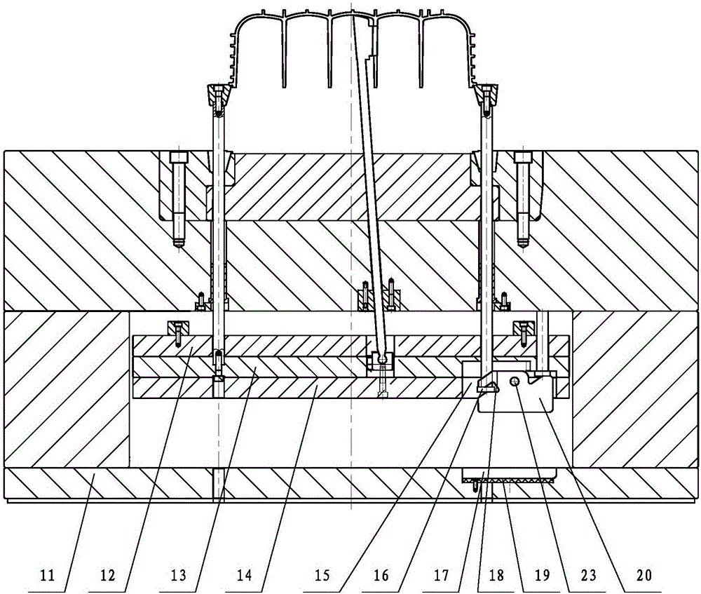
[0024] Depend on Figure 1 to Figure 5 It can be seen from the structural schematic diagram of the mold ejection device of the internal multi-rib product shown in the present invention that it includes a straight ejection mechanism located at the edge of the product 1 and slidably connected in the lower mold assembly, located inside the product 1 and slidably connected in the lower mold assembly The inclined top mechanism inside, the top plate assembly under the lower mold assembly, and the secondary ejection mechanism. There are multiple sets of the straight top mechanism, the lower end of the straight top mechanism is connected to the top plate assembly, and the edge of the upper end is pressed against the bottom end of the product 1 . The number of the inclined roof mechanism depends on the number of through holes 2 on the inner r...


PUM


Abstract

The invention discloses a mold ejection device for products with multiple ribs inside. The mold ejection device comprises straight ejecting mechanisms, oblique ejecting mechanisms, a top plate assembly and at least one set of secondary ejection mechanism; multiple sets of straight ejecting mechanisms are arranged, the lower ends of the straight ejecting mechanisms are connected to the top plate assembly, and the upper end edges of the straight ejecting mechanisms abut against the bottom end of a product (1); the number of the oblique ejecting mechanisms is determined according to the number of through holes (2) in inner rib plates (3) inside the product (1), the lower ends of the oblique ejecting mechanisms are connected to the top plate assembly, and the upper ends of the oblique ejecting mechanisms abut against the inner bottom surface of the product (1); and the secondary ejection mechanisms are rotatably connected to the top plate assembly, and one end of the secondary ejection mechanism is movably connected with the bottom of one set of straight ejection mechanism. After adoption of the structure, during complete demoulding, the stroke of straight ejecting rods is larger than the stroke of oblique ejecting rods, and therefore, an operator can very conveniently take down the product from the straight ejecting rods without damaging the product.

Description

technical field [0001] The invention relates to the technical field of moulds, in particular to a mold ejection device for internal multi-rib products. Background technique [0002] At present, plastic products are used in many parts of automobiles, and these plastic products are usually formed by injection molding through injection molds. However, the structure of many products is very complex, such as figure 1 The shell-shaped product shown in , it has a plurality of transverse protrusions 4 on the outer wall of the product 1, and a plurality of inner ribs 3 are arranged inside the product 1, and one of the inner ribs 3 is also provided with a through hole 2 . When designing the mold, the horizontal protrusion 4 on the outer wall of the product 1 can be removed from the mold by moving the side formwork horizontally, but the design of the through hole 2 on the inner rib 3 cannot be directly removed from the mold, and the inner rib 3 needs to be removed. Make a sloped top...

Claims


Application Information

Patent Timeline
Patent Type & Authority Applications(China)
IPC IPC(8): B29C45/40B29C45/44B29L31/30
CPCB29C45/4005B29C45/44B29L2031/30
Inventor 吴贤益胡腾飞薛强吴彩虹应可国陈晨
Owner NINGBO FANGZHENG TOOL
Learn More