
Gear clutch mechanism and radiotherapy equipment including it

A gear clutch and gear technology, which is applied in the field of medical equipment, can solve the problems that the center distance cannot be guaranteed to be uniform, the moving distance is different, and cannot meet the increasingly strict requirements of the treatment head of radiotherapy equipment, etc., and achieves the effect of a good locking function.

Active Publication Date: 2018-09-21
SHANGHAI UNITED IMAGING HEALTHCARE
View PDF8 Cites 0 Cited by
  • Summary
  • Abstract
  • Description
  • Claims
  • Application Information

AI Technical Summary

Problems solved by technology

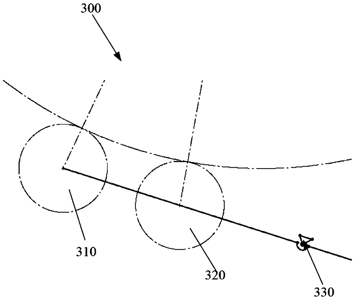
The disadvantage is that the two pinions 310, 320 have different distances from the lever rotation point 330, so that the two pinions 310, 320 move different distances during the meshing process, resulting in the center of the two pinions 310, 320 The pitch cannot be guaranteed to be uniform, which causes the transmission accuracy of the two pinion gears 310, 320 to be different
[0006] It can be seen that the manual input method and the radial clutch used in the prior art have their own defects, and cannot meet the increasingly stringent requirements for the treatment head in radiotherapy equipment.

Method used


Image

  • Gear clutch mechanism and radiotherapy equipment including it
  • Gear clutch mechanism and radiotherapy equipment including it
  • Gear clutch mechanism and radiotherapy equipment including it

Examples


Embodiment 1

[0041] Figure 4 It is a perspective view of Embodiment 1 of the gear clutch mechanism of the present invention.

[0042] Such as Figure 4 As shown, the gear clutch mechanism 400 of the present invention is installed on a base (not shown in the figure), and the gear clutch mechanism 400 includes a driven gear 410 , a guide 420 , a mounting plate 430 , a pushing assembly 440 and a driving gear 450 . Wherein, the driven gear 410 is fixed on the base and can rotate on the base. The guide 420 is also fixed on the base. The mounting plate 430 is disposed above the base through the guide 420 , so that the mounting plate 430 is slidably supported by the guide 420 , for example, the mounting plate 430 can approach or move away from the driven gear 410 under the thrust of the pushing assembly 440 . The pushing assembly 440 is mainly used to push the mounting plate 430 to slide along the guide 420 . A rotatable driving gear 450 is disposed on the mounting plate 430 such that the dr...

Embodiment 2

[0064] Figure 10 It is a structural schematic diagram of Embodiment 2 of the gear clutch mechanism of the present invention.

[0065] Such as Figure 10 As shown, the structure of this embodiment is basically the same as that of Embodiment 1, except that the gear clutch mechanism 500 includes a driven gear 510, a mounting plate 520, a driving gear 530 (not including a detection gear) and a push assembly. The pushing assembly includes a front stopper 540 , a rear stopper 550 and a cam 560 arranged on the mounting plate 520 . Preferably, the rotation centers of the driving gear 530, the driven gear 510, and the cam 560 are located on a straight line.

[0066] Figure 11 It is a schematic diagram of the structural cooperation between the gear clutch mechanism and the treatment head in the radiotherapy equipment of the present invention Figure 1 . Figure 12 It is a schematic diagram of the structural cooperation between the gear clutch mechanism and the treatment head in t...


PUM


Abstract

The invention provides a gear clutch mechanism and radiotherapy equipment including the same. The gear clutch mechanism is mounted at a base and comprises a driven gear, a guiding component, a mounting plate, a driving gear and a pushing assembly, wherein the driven gear is rotatably fixed to the base; the guiding component is fixed on the base; the mounting plate is supported by the guiding component in a sliding manner; the driving gear is rotatably fixed to the mounting plate; the pushing assembly is used for pushing the mounting plate to slide along the guiding component, and when the pushing assembly pushes the mounting plate to slide close to the driven gear, the driving gear moves close to the driven gear until being mutually meshed with the driven gear; and when the pushing assembly pushes the mounting plate to slide away from the driven gear, the driving gear moves far from the driven gear until being mutually separated from the driven gear. The gear clutch mechanism adopts a special cam structure, so that the clutching of the gear in the radial direction can be conveniently realized. By adjusting the profile of the cam, a relatively large dead angle can be formed, and a good locking function can be realized.

Description

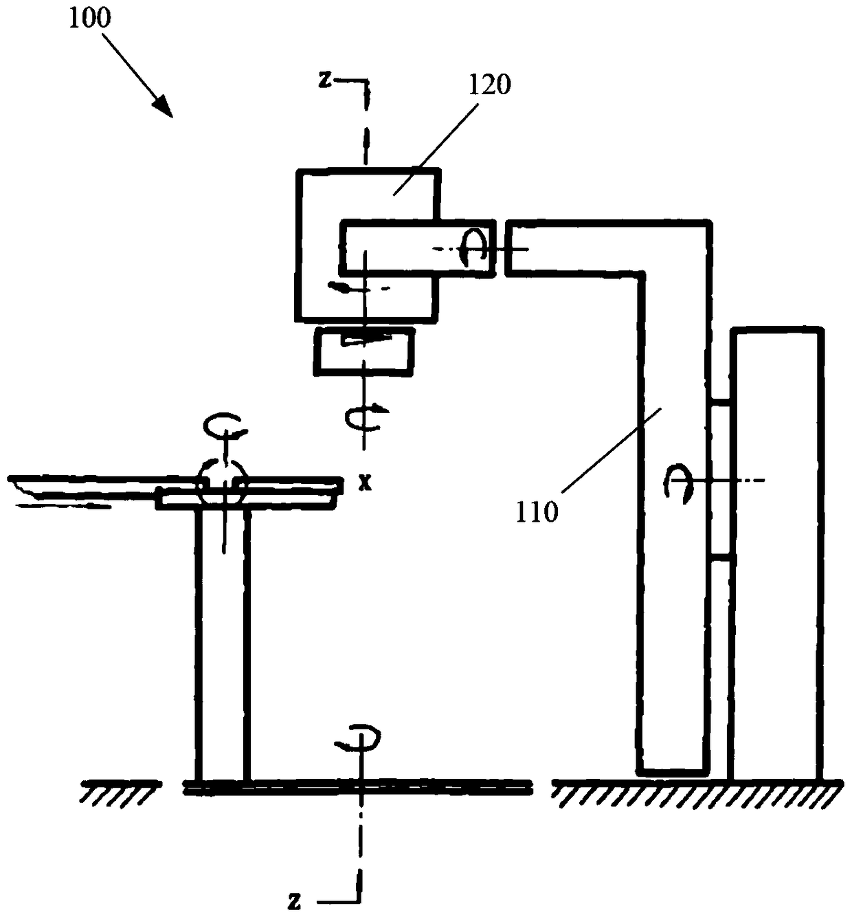
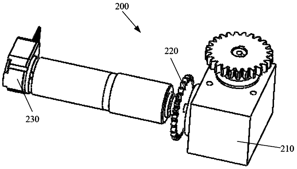
technical field [0001] The invention mainly relates to the field of medical devices, in particular to a gear clutch mechanism and radiotherapy equipment including the same. Background technique [0002] Radiation therapy is currently an important means of treating malignant tumors, usually using a medical linear accelerator. figure 1 is a schematic diagram of an existing medical linear accelerator, such as figure 1 As shown, a conventional medical linear accelerator 100 is mainly composed of a frame 110 and a treatment head 120 (radiation head). In the medical linear accelerator 100 , in order to better simulate the shape of the tumor, the treatment head 120 usually rotates around the Z-axis of the medical linear accelerator 100 . [0003] Due to the high precision and high safety requirements of the medical linear accelerator, the treatment head will be in a self-locking state. Given that therapy heads are high failure systems, they require frequent maintenance and repai...

Claims


Application Information

Patent Timeline
Patent Type & Authority Patents(China)
IPC IPC(8): F16D23/14F16D11/00A61N5/10
Inventor 翟明春
Owner SHANGHAI UNITED IMAGING HEALTHCARE
Learn More