
Automatic weighing device of washing machine

An automatic weighing device and washing machine technology, applied in the field of washing machines, can solve problems such as difficult wiring, large vibration of the washing tub assembly, and high center of gravity

Active Publication Date: 2016-09-28
QINGDAO HAIER WASHING MASCH CO LTD
View PDF7 Cites 0 Cited by
  • Summary
  • Abstract
  • Description
  • Claims
  • Application Information

AI Technical Summary

Problems solved by technology

[0005] Although the above structure can be accurately measured, there are still the following defects: because the load cell is installed on the suspension system, the installation of washing machine components is relatively complicated, wiring is difficult, and there are potential safety hazards; in addition, because the suspension system is mainly used for shock absorption, During the working process, the vibration of the washing bucket assembly is relatively large, resulting in a large change in the pressure of the load cell installed between the spring seat and the sensor seat, shortening the service life
[0007] This structure is equivalent to embedding the existing electronic balance above the shell of the washing machine. Although it can measure the weight of the clothes, the clothes must be placed on the weighing device for measurement before each washing, and then put into the washing machine for washing. Very cumbersome to use; secondly, the device does not measure the amount of water in the washing machine
[0008] Due to the vibration generated by the dehydration of the washing machine, the washing machine is displaced to the inclined surface, especially when the user moves and places it, and the washing machine is large in size, high in the center of gravity, and heavy in quality. Many manufacturers believe that the measurement accuracy of the load cell installed on the foot of the washing machine is not high. The error is large, and it is easy to be damaged. In view of this, the present invention is proposed

Method used


Image

  • Automatic weighing device of washing machine
  • Automatic weighing device of washing machine
  • Automatic weighing device of washing machine

Examples


Embodiment Construction

[0031] The specific implementation manners of the present invention will be further described in detail below in conjunction with the accompanying drawings.

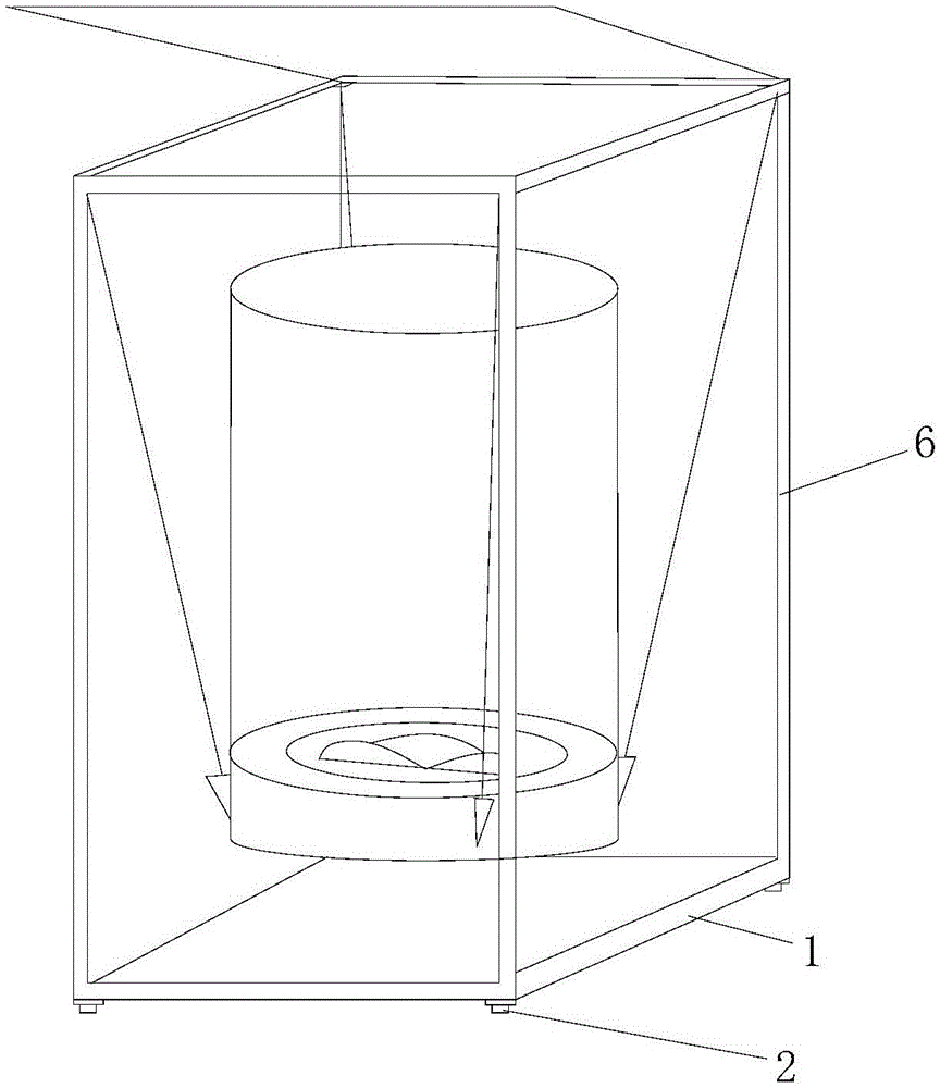
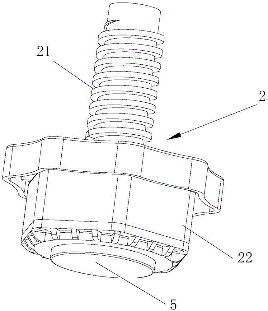
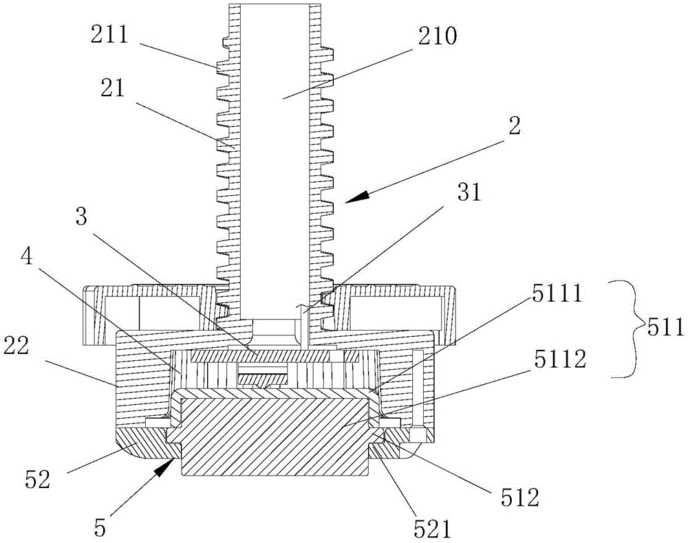
[0032] Such as figure 1 and image 3 As shown, the washing machine automatic weighing device of the present invention is installed under the base 1 of the washing machine, and includes a foot 2 and a load cell 3 installed on the foot 2 (see image 3 ).

[0033] Such as Figure 5 As shown, is a schematic diagram of the foot force model when the washing machine is tilted, where n is the ground, O is the center of gravity of the washing machine, and m is the horizontal plane.

[0034] The gravity of the washing machine is F, the reaction forces on the ground at the feet A and B of the washing machine are F1 and F2 respectively, the length of the bottom side of the washing machine is L=︱AB︱=600mm, the height of the center of gravity is H=︱OC︱=450mm, The horizontal distance between F and F2︱A'D'︱=L2*cosα, the horizontal d...


PUM


Abstract

The invention discloses an automatic weighing device of a washing machine. The device comprises footing installed under a washing machine base and a weighing sensor installed on the footing, wherein a cavity with a downward opening is formed in the bottom of the footing; and the weighing sensor is installed in the cavity by a supporting part in a sealed manner. The footing comprises a connecting part and a supporting part, wherein the connecting part and the supporting part form an integral projecting structure; the connecting part is hollow in the axial direction; the outer wall is equipped with threads; the supporting part is disposed under the connecting part; and the cavity is disposed in the supporting part and communicates with the hollow part of the connecting part. The supporting part comprises a supporting unit and a fixation unit, wherein the fixation unit movably installs the supporting unit in the cavity; the upper end face of the supporting unit is contacted with the weighing sensor; and the lower end face is supported on the ground. The device disclosed by the invention has the advantages that clothes and water in a wash bucket of the washing machine can be weighed automatically; weighing accuracy is high; and weighing errors are small.

Description

technical field [0001] The invention relates to the field of washing machines, in particular to an automatic weighing device for washing machines. Background technique [0002] Existing washing machines are all driven by the motor to rotate the washing tub filled with clothing to work normally, and all have the weighing function of clothing. There are many ways to realize the weighing function of the washing machine: by controlling the motor to reach the first predetermined speed, and making the motor rotate at a constant speed at the first predetermined speed, measure the first torque of the motor at this time, and then control the motor to make the motor rotate from Accelerate from the first predetermined speed to the second predetermined speed, measure the rising torque of the motor when it rises from the first predetermined speed to the second predetermined speed, and finally control the motor to rotate at a constant speed at the second predetermined speed, and measure t...

Claims


Application Information

Patent Timeline
IPC IPC(8): D06F39/00D06F34/18
CPCD06F34/18D06F2103/18D06F2103/04D06F39/125D06F37/20
Inventor 田云张刚金安凯周春霞李峰
Owner QINGDAO HAIER WASHING MASCH CO LTD
Learn More