
Flow speed measurement method and flow speed measurement system

A flow rate measurement and flow rate technology, which is applied in the field of flow rate measurement and flow rate measurement system, can solve the problems of inaccurate measurement, incapable conduction of steam heat, and inability of temperature sensor to detect temperature well

Inactive Publication Date: 2016-09-21
TOKYO ELECTRIC POWER CO HLDG INC
View PDF10 Cites 0 Cited by
  • Summary
  • Abstract
  • Description
  • Claims
  • Application Information

AI Technical Summary

Problems solved by technology

[0004] When the above-mentioned conventional technology is used to measure the steam flow rate, it may not be measured accurately
This is because the thermal conductivity of steam is much lower than that of water, so the heat of the steam flowing in the pipe cannot be transferred to the surface of the pipe, and the temperature cannot be detected well by the temperature sensor.

Method used


Image

  • Flow speed measurement method and flow speed measurement system
  • Flow speed measurement method and flow speed measurement system
  • Flow speed measurement method and flow speed measurement system

Examples


Embodiment Construction

[0032] Hereinafter, several embodiments of the present invention will be described with reference to the drawings. The flow rate measurement system of the present embodiment is capable of measuring, for example, the flow rate of a thermal fluid (for example, steam) flowing in a pipe disposed between a steam production device such as a boiler and a load facility.

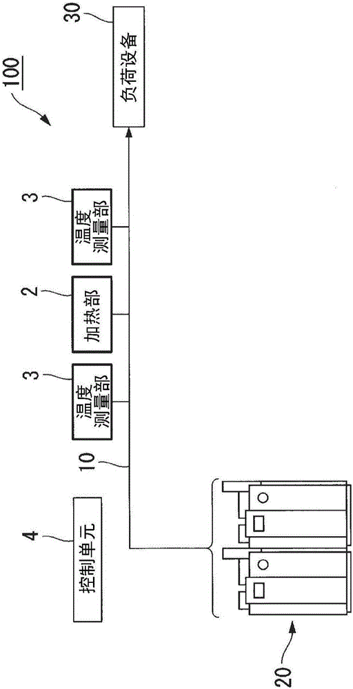
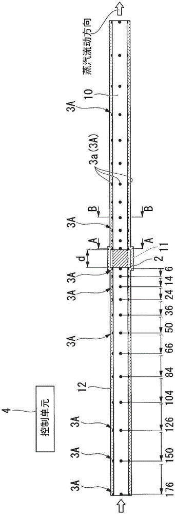
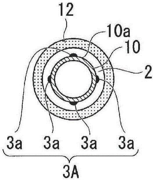
[0033] figure 1 It is a schematic configuration diagram showing the flow velocity measurement system of this embodiment. Figure 2A to Figure 2C It is a block diagram showing a main part of the flow velocity measurement system of this embodiment.

[0034] Such as figure 1 As shown, the flow velocity measurement system 100 of this embodiment includes: a heating unit (heat exchanger) 2 , a temperature measurement unit 3 , and a control unit (flow velocity calculation unit) 4 . exist figure 1 Among them, the pipe 10 is disposed between the steam production device 20 (boiler, etc.) and the load facility 30 . The ste...


PUM


Abstract

A flow speed measurement method according to one embodiment of the present invention involves carrying out heat exchange on a prescribed portion of the surface of a pipe, measuring the surface temperature distribution in the pipe axis direction of the pipe that has had heat exchange carried out on a prescribed portion, and determining the flow speed of thermal fluid flowing inside the pipe on the basis of the measured temperature distribution.

Description

technical field [0001] The invention relates to a flow velocity measurement method and a flow velocity measurement system. [0002] This application claims priority based on the application No. 2014-021298 filed in Japan on February 6, 2014, and incorporates the above content into the present application. Background technique [0003] Conventionally, as a method of measuring the flow rate of a fluid flowing in a pipe, it has been disclosed to use two temperature sensors installed upstream and downstream on the surface of the pipe to detect a change in temperature of the fluid flowing in the pipe, and to calculate the pipe flow rate based on the time difference at this time. A technique such as the flow rate of the fluid flowing inside (for example, refer to Patent Document 1). [0004] When the above-mentioned conventional techniques are used to measure the steam flow rate, there are cases where accurate measurement cannot be performed. This is because the thermal conducti...

Claims


Application Information

Patent Timeline
Patent Type & Authority Applications(China)
IPC IPC(8): G01F1/684G01F1/688
CPCG01F1/684G01F1/688
Inventor 梅沢修一田中胜彦横坂雅树宫内亮二
Owner TOKYO ELECTRIC POWER CO HLDG INC
Learn More