Eureka AIR delivers breakthrough ideas for toughest innovation challenges, trusted by R&D personnel around the world.

Air-Coupled Low-Profile Circularly Polarized Dielectric Lens Antenna

A dielectric lens antenna and air-coupling technology, applied in the microwave field, can solve the problems of large variation of reflection coefficient amplitude and phase with frequency, impedance bandwidth, narrow circular polarization bandwidth, antenna 3dB gain bandwidth limitation, etc., to improve impedance bandwidth, Achieve low profile, reduced distance effects

Active Publication Date: 2018-08-14
NANJING UNIV OF POSTS & TELECOMM
View PDF2 Cites 2 Cited by
  • Summary
  • Abstract
  • Description
  • Claims
  • Application Information

AI Technical Summary

Problems solved by technology

[0004] 1. The traditional circularly polarized lens antenna has relatively narrow impedance bandwidth and circularly polarized bandwidth, and can only work in a small frequency band;
[0005] 2. The partial reflection surface of the traditional circularly polarized lens antenna has a higher reflection phase in the antenna working frequency band, which makes the antenna profile height higher
And because the magnitude and phase of the reflection coefficient of the partially reflective surface vary greatly with frequency, the 3dB gain bandwidth of the antenna is limited

Method used


Image

  • Air-Coupled Low-Profile Circularly Polarized Dielectric Lens Antenna
  • Air-Coupled Low-Profile Circularly Polarized Dielectric Lens Antenna
  • Air-Coupled Low-Profile Circularly Polarized Dielectric Lens Antenna

Examples


Embodiment Construction

[0026] Below in conjunction with accompanying drawing, technical scheme of the present invention is described in further detail:

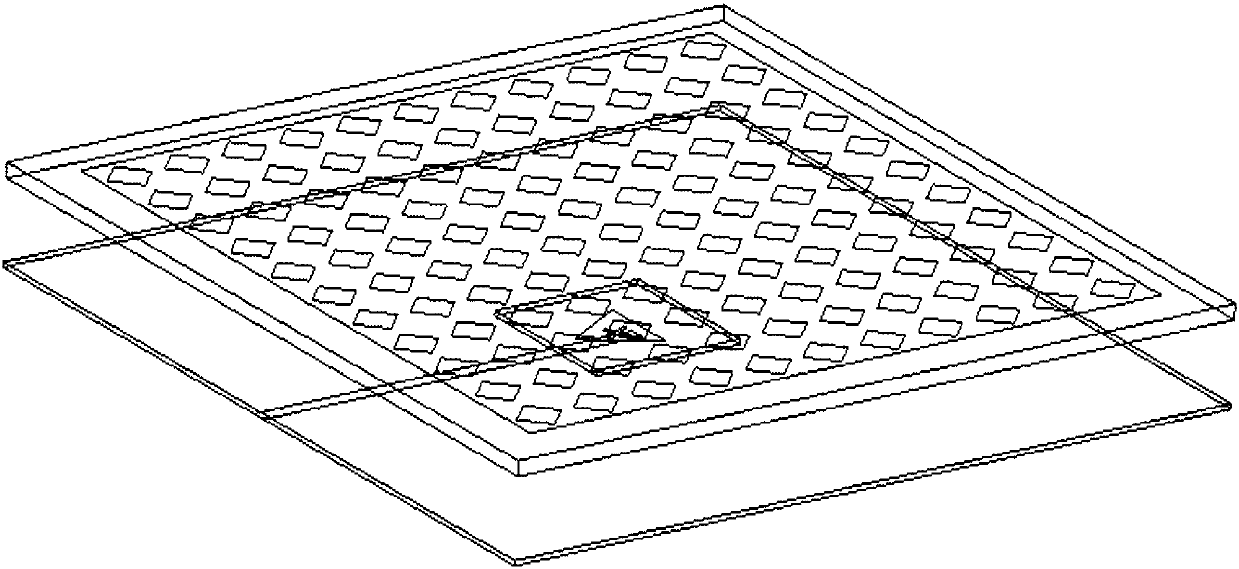
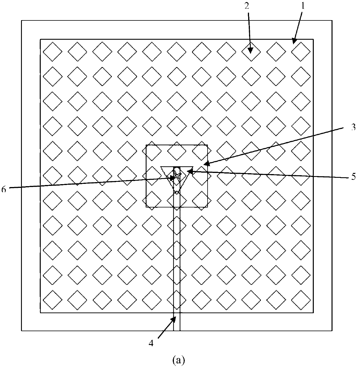
[0027] The invention provides an air-coupled low-profile circularly polarized dielectric lens antenna composed of three layers of dielectric plates, such as Figure 1 to Figure 6 shown. A layer of square metal layer is coated on the upper surface of the top dielectric plate, and a periodic diamond-shaped slit structure is opened on the square metal layer. Moreover, the square metal layer does not cover the entire upper surface of the top dielectric board, and there is a part of the surrounding area that is not covered with metal, which is used for later punching and fixing. The shape and size of the rhombic slot affects the magnitude and phase of its reflection coefficient, thereby affecting the gain performance of the antenna. The width and side length of the periodic diamond-shaped slit determine the working frequency band in which the antenna ...


PUM


Abstract

The invention discloses an air-coupled low-profile circularly-polarized dielectric lens antenna. The air-coupled low-profile circularly-polarized dielectric lens antenna is composed of three layers of dielectric plates, a square metal layer is arranged on the upper surface of the dielectric plate on the top layer, and a periodic rhombus gap is further formed in the square metal layer; a metal patch in the shape of an equilateral triangle is arranged on the lower surface of the dielectric plate on the middle layer, and the center of the metal patch is overlapped with the center of the dielectric plate on the middle layer; a microstrip line for feeding extending to the center along one side of the dielectric plate on the bottom layer is arranged on the lower surface of the dielectric plate on the bottom layer; the upper surface of the dielectric plate on the bottom layer is covered with a metal layer as an earth plate, and a cross-shaped gap is formed in the central position of the earth plate. According to the air-coupled low-profile circularly-polarized dielectric lens antenna, the impedance bandwidth, gain bandwidth and circular polarization bandwidth of the dielectric lens antenna are greatly improved. Moreover, through the design of a partial reflection surface, the reflection phase of the partial reflection surface in an antenna working frequency band is reduced, so that the height of the antenna is reduced, and low profile of the antenna is realized.

Description

technical field [0001] The invention relates to an air-coupled low-profile circularly polarized dielectric lens antenna, which belongs to the field of microwave technology. Background technique [0002] With the rapid development of modern wireless communication technology, the requirements for miniaturized and planar antennas are getting higher and higher, and the requirements for their gain are also getting higher and higher. In many cases, it is also necessary for the antenna to be able to generate circularly polarized waves to cope with different weather conditions. Therefore, a method of increasing the gain of the antenna by adding a part of the radiation surface in the radiation direction of the antenna is proposed. [0003] There are two problems in the design of traditional dielectric lens antennas: [0004] 1. The traditional circularly polarized lens antenna has relatively narrow impedance bandwidth and circularly polarized bandwidth, and can only work in a small...

Claims


Application Information

Patent Timeline
Patent Type & Authority Patents(China)
IPC IPC(8): H01Q1/38H01Q1/50H01Q15/14
CPCH01Q1/38H01Q1/50H01Q15/14
Inventor 许锋曹奎根
Owner NANJING UNIV OF POSTS & TELECOMM
Why Eureka
Eureka Blog
Learn More