
Telescopic device

A telescoping device and connecting sleeve technology, which is applied in the connection of rods, connecting components, supporting machines, etc., can solve the problems of easy slipping, poor stability of the tripod, and large shaking range, etc., to achieve simple and fast operation, improve stability, and stabilize sex high effect

Inactive Publication Date: 2016-09-21
中山市欧栢摄影器材有限公司
View PDF6 Cites 5 Cited by
  • Summary
  • Abstract
  • Description
  • Claims
  • Application Information

AI Technical Summary

Problems solved by technology

[0002] The telescopic devices such as tripods, selfie sticks and monopods in the prior art generally have two types of eccentric tube locking and thread locking, and the eccentric tube telescopic devices are easy to loosen and the stability is not strong
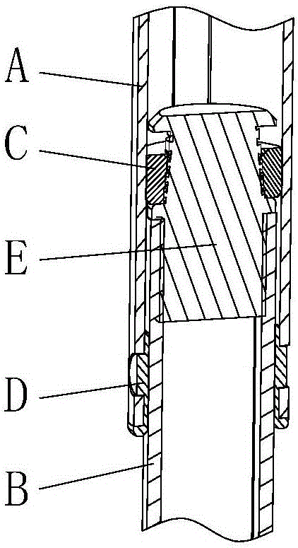
The current thread expansion device such as figure 1 As shown, it includes the outer tube A and the inner tube B, the connecting sleeve C and the locking cone E are installed between the outer tube A and the inner tube B, the connecting sleeve C is an open ring, the inner wall of the connecting sleeve C and the locking cone The outer wall of E is provided with a corresponding thread, and a gear ring D is installed at the lower end of the outer tube A. The connecting sleeve C can slide axially in the outer tube A and cannot rotate circumferentially, and locks the cone head E and the upper end of the inner tube B. Fixed connection, locking cone E and inner tube B cannot rotate relative to each other, rotating inner tube B drives locking cone E to rotate, and the thread cooperation between connecting sleeve C and locking cone E makes connecting sleeve C relatively locked The tightening cone E moves axially, and the tapered surface between the connecting sleeve C and the locking cone E locks and fixes the outer tube A and the inner tube B. On the one hand, this telescopic device has a certain distance from the lower end of the outer tube A. There is a long gap between the lower end of the outer tube A and the inner tube B, and the swing between the leg tubes after locking is relatively large, resulting in poor stability of the tripod. On the other hand, the connecting sleeve C relies on The inner part of the support outer tube is fixed, it is easy to slip, and the locking force is not enough

Method used


Image

  • Telescopic device
  • Telescopic device
  • Telescopic device

Examples


Embodiment Construction

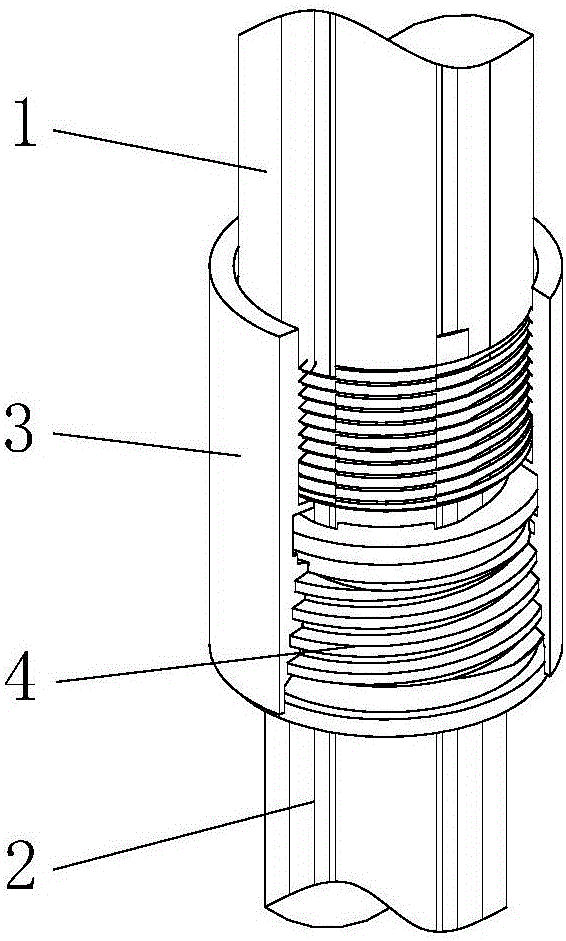
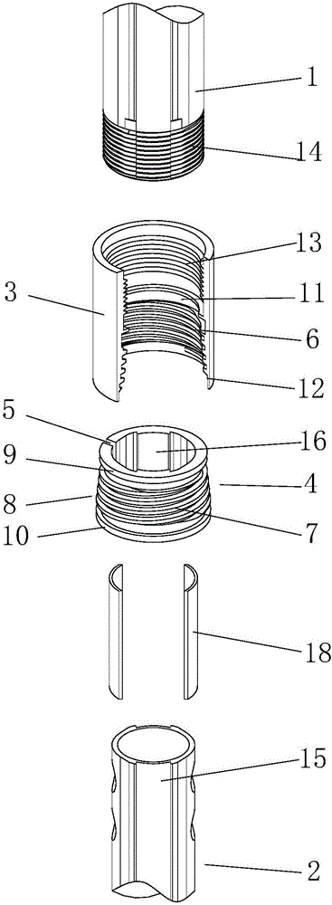
[0029] refer to Figure 1 to Figure 13 , a telescopic device, comprising an outer tube 1, an inner tube 2 and a connecting sleeve 3, the upper end of the inner tube 2 extends into the outer tube 1, the upper part of the connecting sleeve 3 and the lower end of the outer tube 1 Fixed connection, the lower part of the connecting sleeve 3 is installed with a locking sleeve 4 set on the inner tube 2, the locking sleeve 4 is provided with an axial opening 5 to form a C-shaped open ring, so The inner wall of the connecting sleeve 3 is provided with an internal thread 6, the outer wall of the locking sleeve 4 is provided with an external thread 7, the outer wall of the locking sleeve 4 is provided with a tapered portion 8, the inner tube 2 and the locking An anti-rotation structure is arranged between the tight sleeves 4, and the anti-rotation structure prevents the relative circumferential rotation between the inner tube 2 and the locking sleeve 4, so that the inner tube 2 and the l...


PUM


Abstract

The invention discloses a telescopic device which comprises an outer tube, an inner tube and a connecting sleeve, wherein the upper end of the inner tube extends into the outer tube; the upper part of the connecting sleeve is fixedly connected with the lower end of the outer tube; a locking sleeve which sleeves on the inner tube is installed in the lower part of the connecting sleeve; an opening in an axial direction is formed in the locking sleeve; a conical part is arranged on the outer wall of the locking sleeve; and a rotation stopping structure is arranged between the inner tube and the locking sleeve. According to the telescopic device, when the inner tube rotates, threads between the connecting sleeve and the locking sleeve make the locking sleeve move in the axial direction, the inner wall of the connecting sleeve extrudes the conical part of the locking sleeve to make the locking sleeve shrink towards the axis and lock the inner tube, and locking or unlocking can be realized by rotating the inner tube; the telescopic device between the outer tube and the inner tube is arranged at the lower end of the outer tube, and a longer interval section does not exist between the lower end of the outer tube and the inner tube, so that shaking cannot occur between the outer tube and the inner tube after locking is finished; and the locking force of a leg tube is strong, the stability is high, the operation is simple and rapid, and the stability of a product can be effectively improved.

Description

technical field [0001] The invention relates to a photographic equipment, in particular to a tripod leg tube telescopic device. Background technique [0002] Telescopic devices such as tripods, selfie sticks and monopods in the prior art generally have two types of eccentric tube locking and thread locking, and the eccentric tube telescopic devices are easy to loosen and have poor stability. The current thread expansion device such as figure 1 As shown, it includes the outer tube A and the inner tube B, the connecting sleeve C and the locking cone E are installed between the outer tube A and the inner tube B, the connecting sleeve C is an open ring, the inner wall of the connecting sleeve C and the locking cone The outer wall of E is provided with a corresponding thread, and a gear ring D is installed at the lower end of the outer tube A. The connecting sleeve C can slide axially in the outer tube A and cannot rotate circumferentially, and locks the cone head E and the uppe...

Claims


Application Information

Patent Timeline
IPC IPC(8): F16B7/10F16B7/18F16B7/04F16M11/32F16M13/04
CPCF16B7/10F16B7/0406F16B7/187F16M11/32F16M13/04F16M2200/08
Inventor 张奉果
Owner 中山市欧栢摄影器材有限公司
Learn More