


Quick Research
Generate reliable direction feasibility study reports for your R&D in just a few steps.

Technical Q&A
Discover and master advanced knowledge NOW. Basics, ideas, possibilities, all at once.

Find Solutions
As an expert in R&D theories, this can generate solutions to your technical problems instantly.

Evaluate Feasibility
Analyze your overall solution with one click, know your potential R&D risks in advance.

Monitor Landscape
Get weekly tech updates, stay abreast of the latest tech innovations and key insights.
Attachment member, and seat equipped with airbag module
A technology for installing components and airbags, which is applied to vehicle components, vehicle seats, vehicle safety arrangements, etc., and can solve the problems of complicated structure of suspending wires and complicated installation steps.
- Summary
- Abstract
- Description
- Claims
- Application Information
AI Technical Summary
Problems solved by technology
Method used
Image

Examples
no. 1 Embodiment approach
[0111] First, regarding the mounting member according to the first embodiment of the present invention, refer to Figure 1-Figure 11 while explaining.
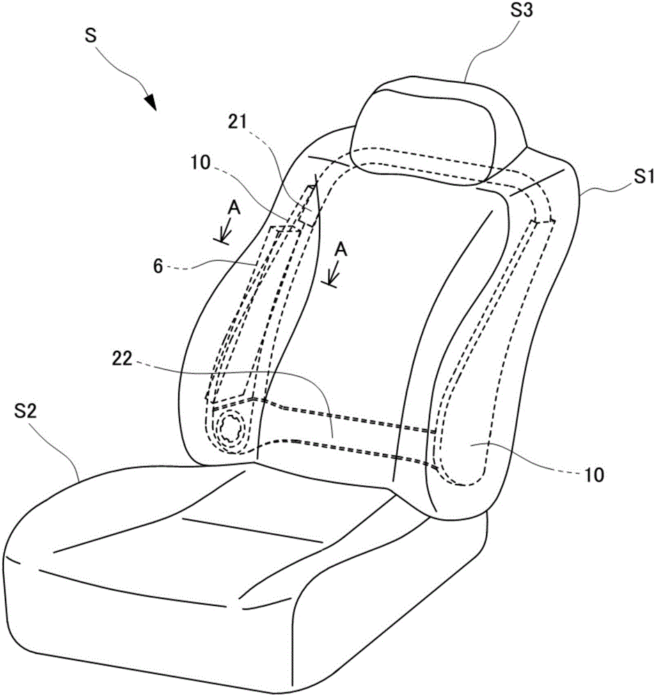
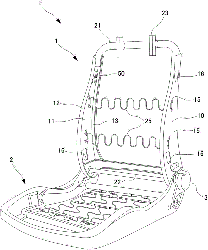
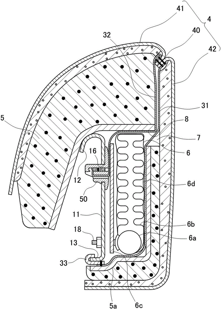
[0112] figure 1 An external view of a seat equipped with an airbag module according to an embodiment of the present invention. figure 2 A perspective view of a seat frame of a seat equipped with an airbag module according to the first embodiment of the present invention. image 3 for figure 1 The A-A sectional view of is an explanatory view showing the state in which the fabric is connected to the side frame by the mounting member according to the first embodiment of the present invention. Figure 4 It is an explanatory diagram showing the state where the decorative cover and fabric according to the first embodiment of the present invention are sewn together to the ruptured portion. Figure 5 It is a perspective view of the attachment member concerning 1st Embodiment of this invention. Figure 6 It is a plan view of the ...
no. 2 Embodiment approach
[0210] Next, regarding the attachment member for attaching the guide member according to the second embodiment of the present invention to the side frame and the airbag module equipped seat provided with the attachment member, refer to Figure 12-Figure 17 while explaining.
[0211] In addition, below, about the structure which overlaps with the said embodiment, the same code|symbol is attached|subjected and the description is abbreviate|omitted, and the difference with the said embodiment is clarified.
[0212] Figure 12 A perspective view of a seat frame of a seat equipped with an airbag module according to a second embodiment of the present invention. Figure 13 It is a perspective view of the attachment member concerning 2nd Embodiment of this invention. Figure 14 It is a plan view of the mounting member according to the second embodiment of the present invention. Figure 15 It is a bottom view of the mounting member according to the second embodiment of the present i...
no. 3 Embodiment approach
[0246] Next, regarding the vehicle seat according to the third embodiment, which corresponds to the airbag module-equipped seat of the present invention and includes a mounting member for mounting the guide member according to the present embodiment to the side frame, refer to Figure 18-Figure 26 while explaining.
[0247] In addition, below, about the structure which overlaps with the said embodiment, the same code|symbol is attached|subjected and the description is abbreviate|omitted, and the difference with the said embodiment is clarified.
[0248] Figure 18 A perspective view of a seat frame of an airbag module-equipped seat according to a third embodiment of the present invention, Figure 19 Equipping the seat with the airbag module according to the third embodiment figure 1 A-A sectional view of is an explanatory view showing a state in which fabric is connected to a side frame by an attachment member according to a third embodiment of the present invention, Figur...
PUM
 Abstract
Description
Claims
Application Information
 - R&D Engineer
- R&D Manager
- IP Professional
- Industry Leading Data Capabilities
- Powerful AI technology
- Patent DNA Extraction
Browse by: Latest US Patents, China's latest patents, Technical Efficacy Thesaurus, Application Domain, Technology Topic, Popular Technical Reports.
© 2024 PatSnap. All rights reserved.Legal|Privacy policy|Modern Slavery Act Transparency Statement|Sitemap|About US| Contact US: help@patsnap.com